Spinal implant and method of use

a technology of spinal disc and implant, which is applied in the field of spinal disc implant, can solve the problems of requiring major open surgery, sacrificing mobility, and unable to achieve the effect of achieving balan

Active Publication Date: 2008-06-05
REX MEDICAL LP
View PDF93 Cites 191 Cited by
  • Summary
  • Abstract
  • Description
  • Claims
  • Application Information

AI Technical Summary

Benefits of technology

[0012]The present invention also provides a method of minimally invasively inserting a spinal implant in a disc space. The method comprises providing a delivery instrument containing the spinal implant in a first configuration, the spinal implant having a plurality of hinged sections and a balloon connected thereto, inserting the delivery instrument to the disc space, deploying the implant from the delivery instrument to position the implant in the disc space, expanding the balloon to maintain the hinged sections in a substantially horseshoe shaped configuration, and removing the delivery instrument and leaving the implant in place.

Problems solved by technology

Thus, to achieve stability, they sacrifice mobility.
To date, attempts to strike such balance have met with limited success, with the artificial disc providing either stability or mobility, but not both.
Additionally, in many intervertebral procedures, major open surgery is required.

Method used


Image

  • Spinal implant and method of use
  • Spinal implant and method of use
  • Spinal implant and method of use

Examples


Embodiment Construction

[0025]Referring now in detail to the drawings where like reference numerals identify similar or like components throughout the several views, several different embodiments of the spinal implant of the present invention are described herein.

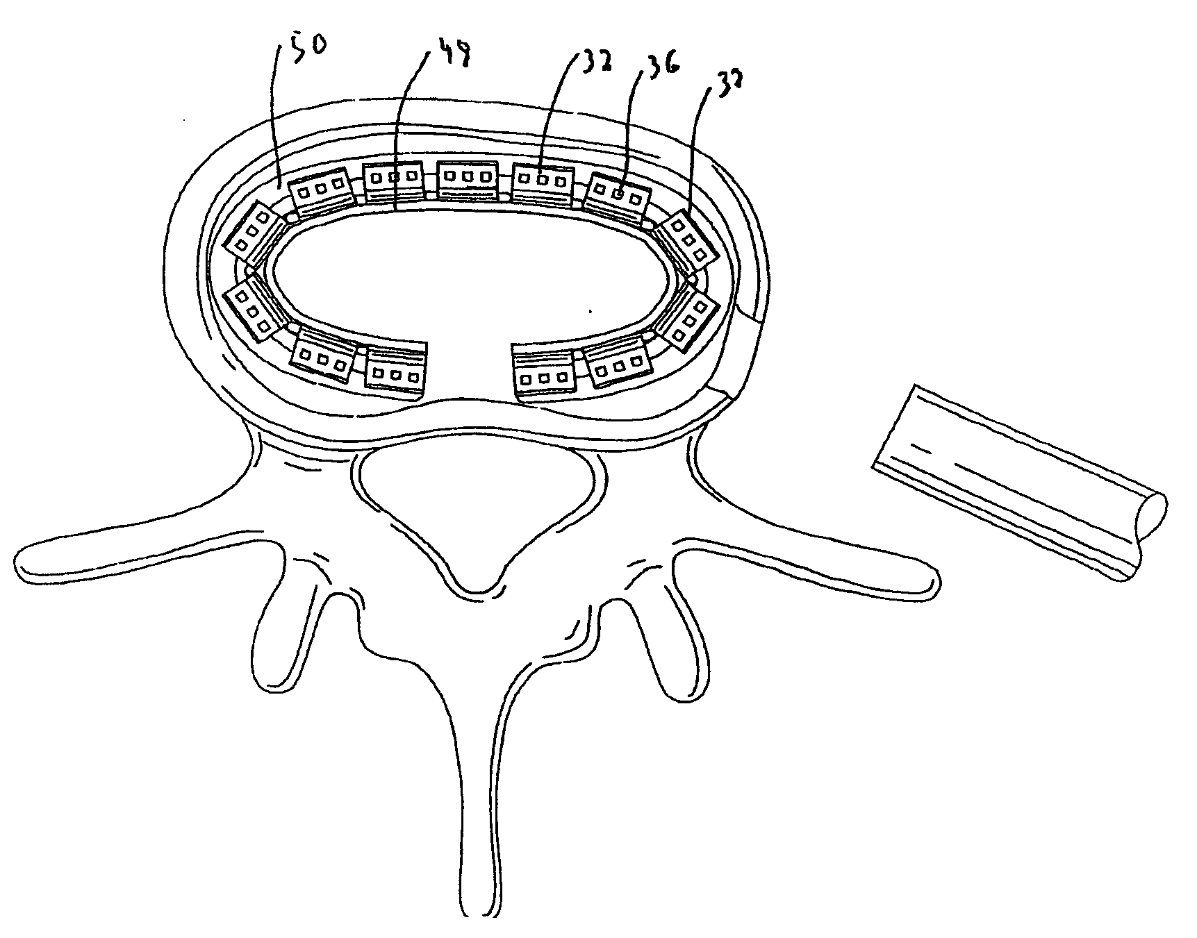
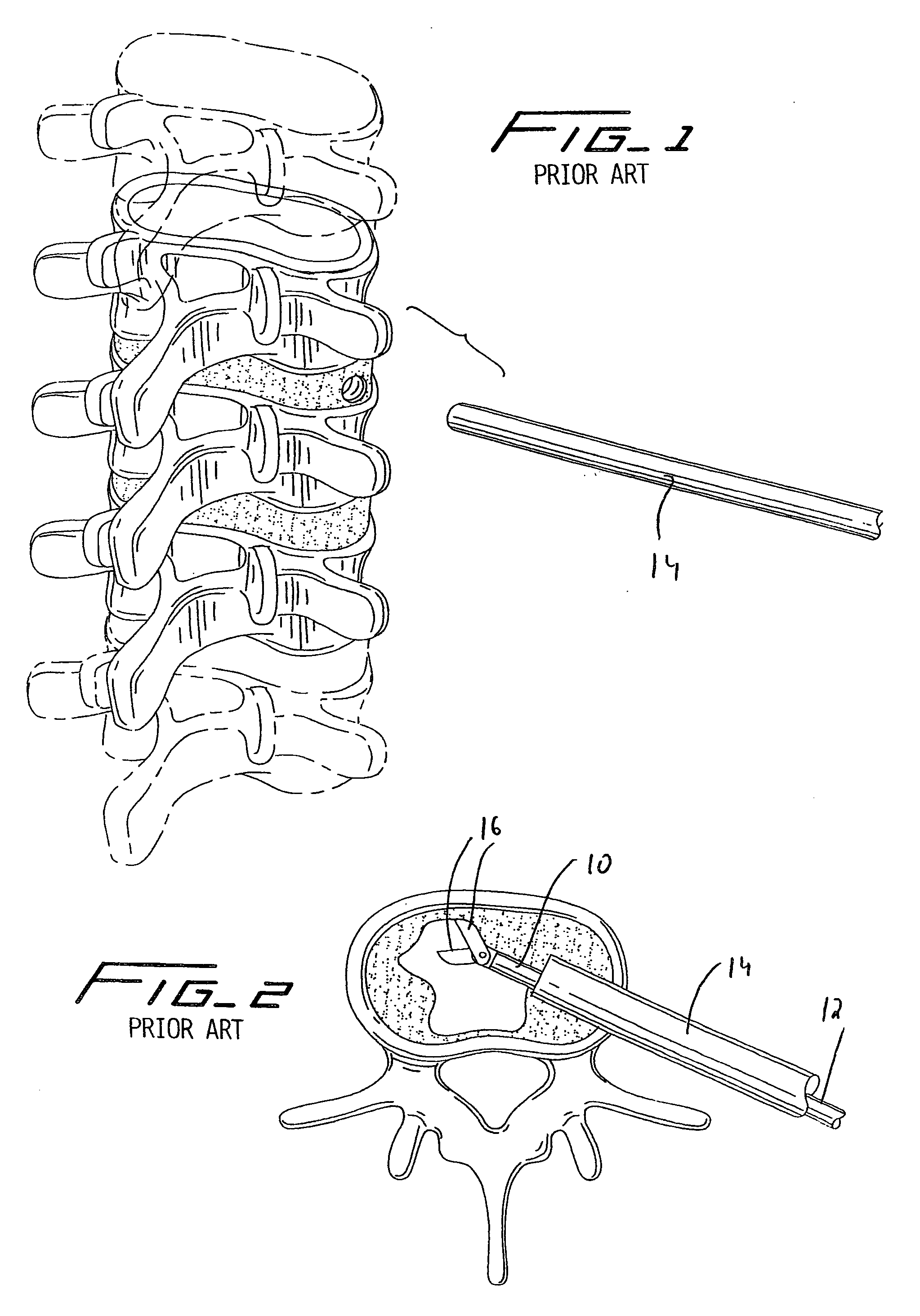
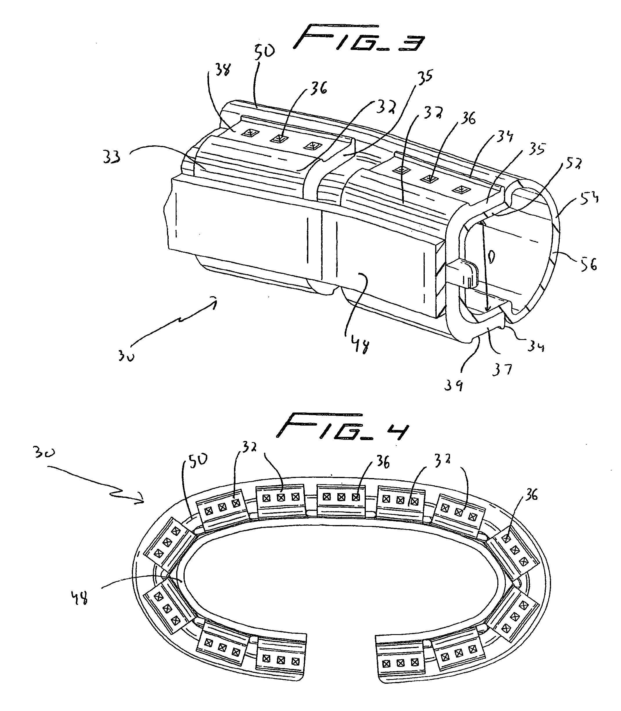
[0026]The spinal implants of the present invention are designed to be inserted minimally invasively into the disc space, thus enabling a smaller incision to be used in the procedure. This is achieved by the implants being deflectable laterally to a substantially linear configuration. That is, the implant is in a more straightened shape to enable minimally invasive insertion through a cannula. Once ejected from the delivery instrument at the desired site, i.e. the disc space between adjacent vertebrae, the balloon will be filled and the implant maintained in a curved configuration. Implanted in the disc space, the spinal implant is radially compressible in response to vertebral loads placed thereon.

[0027]Turning first to the instrumentation for min...


PUM

PropertyMeasurementUnit
lengthaaaaaaaaaa
areaaaaaaaaaaa
stabilityaaaaaaaaaa

Abstract

A spinal implant having a series of sections or units hinged together and a balloon connected to at least some of the sections, the balloon having a curved configuration. The implant has a first delivery configuration and a second curved placement configuration, wherein it has a more linear configuration in the first delivery configuration than in the second curved configuration. The implant assumes the first delivery configuration during delivery to the disc space and maintains the curved configuration after placement within the disc space. The curved configuration can result from filling or expanding the balloon.

Description

[0001]This application claims priority from provisional application Ser. No. 60 / 859,357 filed Nov. 16, 2006, the entire contents of which is incorporated herein by reference.BACKGROUND [0002]1. Technical Field[0003]This application relates to a spinal implant and more particularly to a spinal disc implant that can be inserted minimally invasively.[0004]2. Background of Related Art[0005]After removal of the intervertebral disc, it has been recognized that the disc space needs to be filled between the adjacent vertebrae. There are two approaches in the prior art to fill the space: one involving placement of a fusion cage and the other involving an artificial disc. Fusion cages are essentially metallic cages packed with bone to promote bone ingrowth. The fusion cages, designed to promote fusion, provide support between the vertebrae, but eliminate motion. Thus, to achieve stability, they sacrifice mobility.[0006]Artificial disc prostheses of the prior art take many forms. Each form is ...

Claims


Application Information

Patent Timeline
Patent Type & Authority Applications(United States)
IPC IPC(8): A61F2/44
CPCA61F2002/4415A61F2002/30841A61F2002/30092A61F2002/30571A61F2220/0091A61F2/441A61F2220/0033A61F2002/30131A61F2/442A61F2002/30461A61F2002/30584A61F2230/0013A61F2310/00017A61F2002/30471A61F2310/00023A61F2002/30579A61F2310/00796A61F2220/0075A61F2002/30378A61F2210/0014A61F2/30767A61F2/44A61F2/4611A61F2002/30428A61F2002/30467A61F2002/30581A61F2002/4485
Inventor MCGUCKIN, JAMES F.
Owner REX MEDICAL LP
Why Eureka
Try Eureka