Brake rotor with ceramic matrix composite friction surface plates

Inactive Publication Date: 2008-06-12
STARFIRE SYST
View PDF31 Cites 72 Cited by
  • Summary
  • Abstract
  • Description
  • Claims
  • Application Information

AI Technical Summary

Problems solved by technology

As a consequence, cast iron brake rotors are often heavy.
Furthermore, a relatively large amount of energy is required to accelerate and decelerate the large, heavy, cast iron brake rotors that are found in most passenger vehicles.
The weight of the rotors also increases the

Method used


Image

  • Brake rotor with ceramic matrix composite friction surface plates
  • Brake rotor with ceramic matrix composite friction surface plates
  • Brake rotor with ceramic matrix composite friction surface plates

Examples


Embodiment Construction

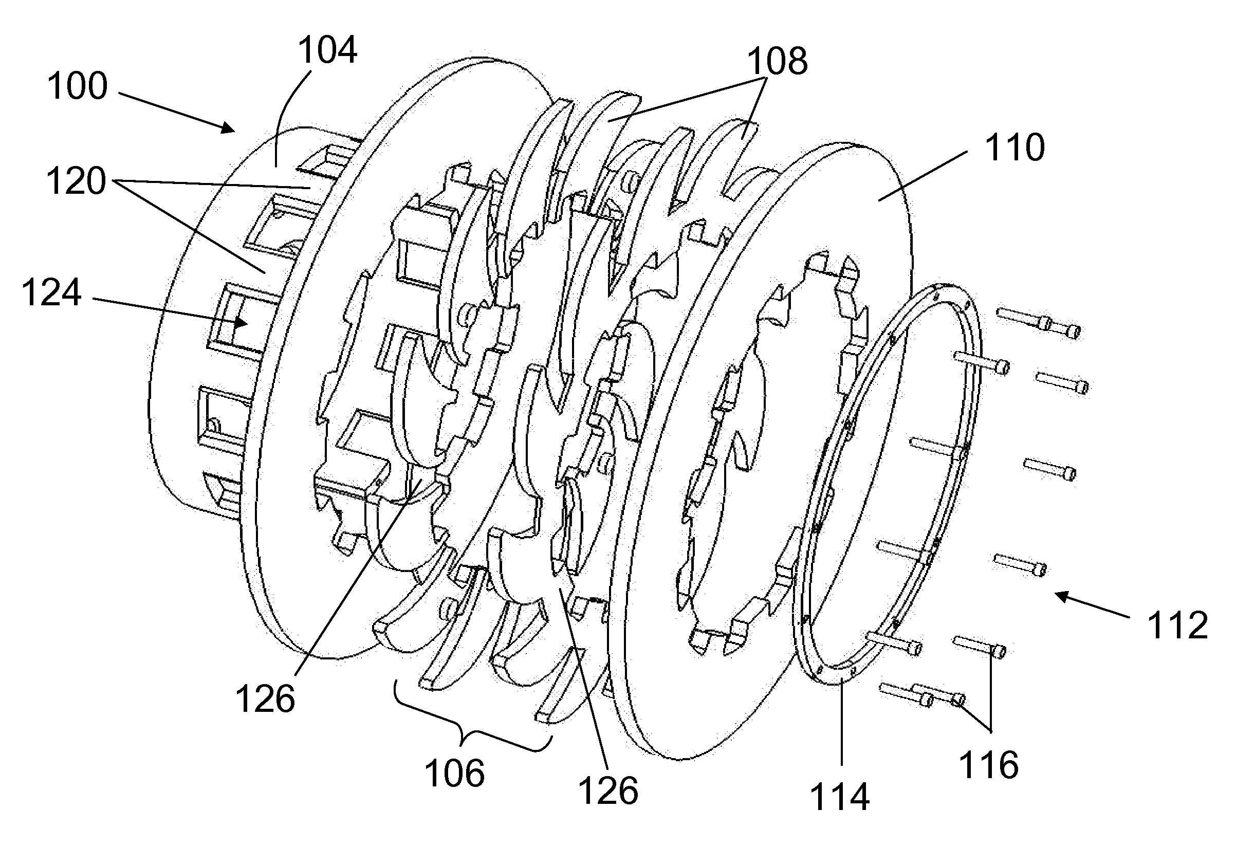
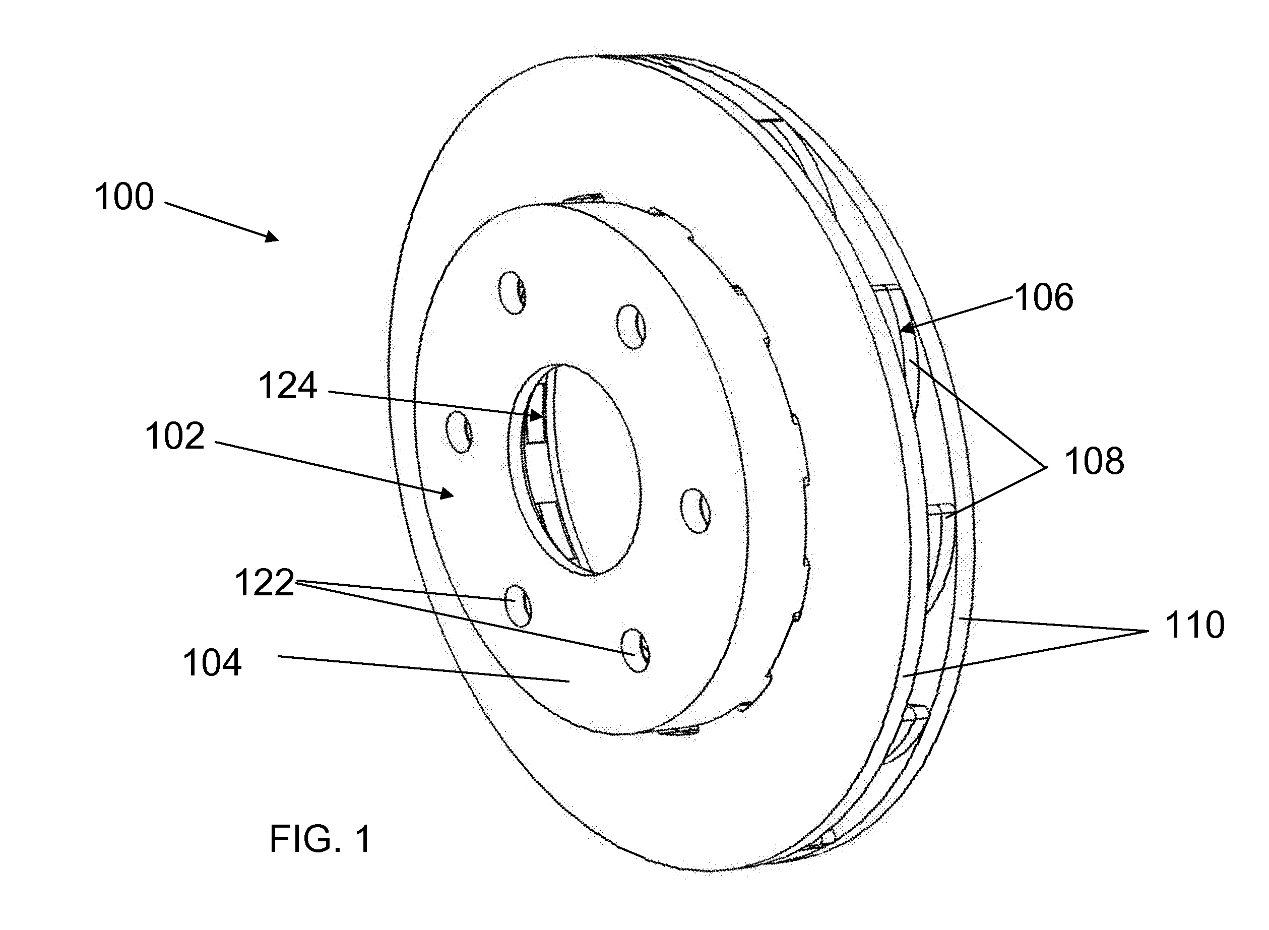
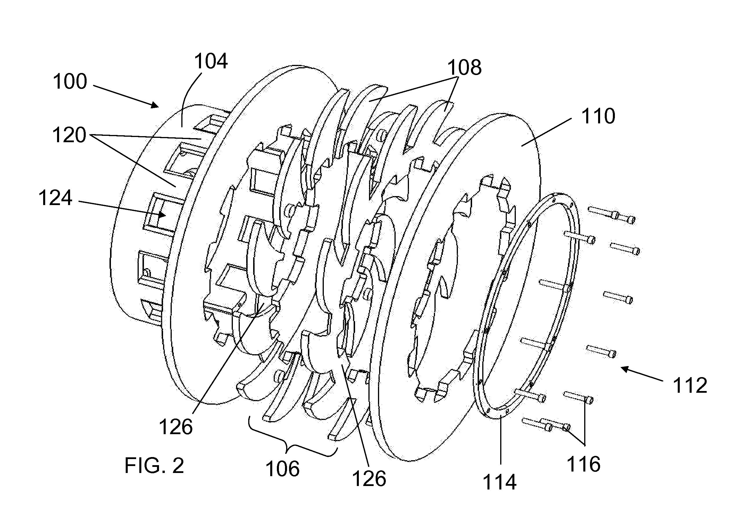
[0016]Turning to FIGS. 1-3, a brake rotor 100 according to embodiments of the disclosure is shown. Brake rotor 100 comprises: a rotor hat 102, a ventilation disc 106 having a plurality of cooling vanes 108 extending therefrom, a ceramic matrix composite (CMC) friction surface plate 110 on each side of ventilation disc 108, and a fastener 112 (FIGS. 2-3) for holding CMC friction surface plates 110 to rotor hat 102. During operation, rotor hat 102 attaches to an axle of, for example, an automobile, and provides venting and an attachment system for CMC friction surface plates 110. Fastener 112 is designed to hold CMC friction surface plates 110 with ventilation disc 106 therebetween against rotor hat 102. Each of these components and their operation will be described in further detail below.

[0017]As shown in FIGS. 1-3, rotor hat 102 includes a central hub 104 having a plurality of splines 120 extending therefrom. Splines 120 create venting openings 124 therebetween. Venting openings 12...


PUM


Abstract

The disclosure relates to structures and a method for providing an air cooled rotor with ceramic-metal composite friction surface plates, and in particular to a brake rotor including a rotor hat; a ventilation disc having a plurality of cooling vanes extending therefrom; a ceramic matrix composite (CMC) friction surface plate on each side of the ventilation disc; and a fastener for holding the CMC friction surface plates and the ventilation disc to the rotor hat.

Description

[0001]This application claims the priority of U.S. Provisional Application No. 60 / 869,452, filed Dec. 11, 2006, under 35 USC 119(e), which is hereby incorporated by reference.BACKGROUND[0002]1. Field of the Disclosure[0003]The field of disclosure relates generally to braking components.[0004]2. Related Art[0005]Brake rotors are components of disc brake systems used in vehicles. Generally, brake rotors include a braking surface that is frictionally engaged by brake pads mounted on calipers. The size, weight, and other attributes of brake rotors are highly variable. Brake rotors are designed to provide adequate braking forces to control the vehicle. Also, brake rotors must be designed with an acceptable service life. A passenger vehicle, for example, typically utilizes relatively large and heavy brake rotors to provide the service life and braking forces required by such a vehicle.[0006]Commonly used brake rotors are often manufactured from cast iron, which has acceptable hardness and...

Claims


Application Information

Patent Timeline
IPC IPC(8): F16D65/12
CPCF16D65/122F16D65/123F16D65/126F16D65/128F16D2200/0047F16D2065/1316F16D2065/1328F16D2065/1356F16D2200/0039F16D69/023
Inventor BASIRICO, JOHN T.BONGIO, EDWARD V.
Owner STARFIRE SYST
Why Eureka
Try Eureka