Change aggregation via timestamps

a technology of change aggregation and timestamps, applied in the direction of instruments, etc., can solve the problem that the prior art process of monitoring the order table alone misses important changes to the business obj

Inactive Publication Date: 2008-06-19
IBM CORP
View PDF14 Cites 18 Cited by
  • Summary
  • Abstract
  • Description
  • Claims
  • Application Information

AI Technical Summary

Problems solved by technology

Consequently, the prior art process of monitoring the Ord...

Method used


Image

  • Change aggregation via timestamps
  • Change aggregation via timestamps
  • Change aggregation via timestamps

Examples


Embodiment Construction

)

[0029]In describing the preferred embodiment of the present invention, reference will be made herein to FIGS. 1-10 of the drawings in which like numerals refer to like features of the invention.

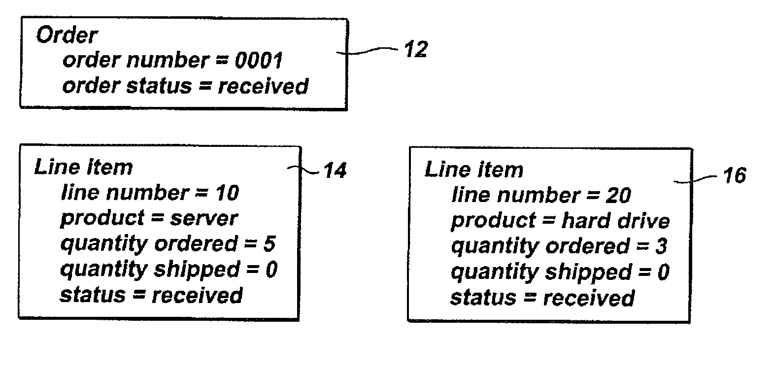
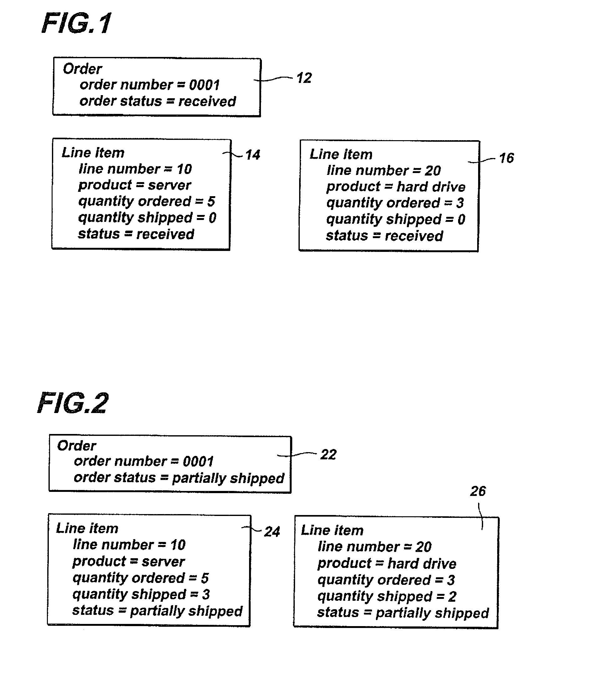
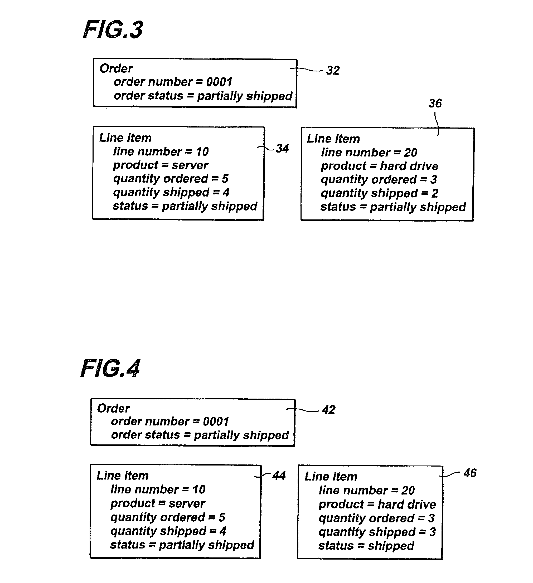
[0030]The present invention addresses the issue of relational database status when only a portion of the order is satisfied. Two date / time columns are added to each row in the database table. These date / time columns are generally referred to as ‘timestamps,’ and represent the time the row was inserted into the database, and the time the row was last updated. The example above is discussed below with the additional implementation of the insert and update timestamps.

[0031]FIG. 6 depicts a relational database representation of an order with insert and update timestamps applied to the order status 62 and to each line item designator 64, 66. In similar fashion to the prior art example, a customer orders five servers and three hard drives. This is represented as one order 62 having two line it...


PUM


Abstract

A method of aggregating changes in an order status database system teaching the method steps of identifying the order and the order status, where the order status includes an insert timestamp and an update timestamp; identifying individual line items (products) that together form the order, each line item identifying the quantity requested, quantity shipped, and status shipped, with individual insert timestamps and update timestamps; and updating the order and line item insert and update timestamps whenever a line item is updated.

Description

BACKGROUND OF THE INVENTION[0001]1. Field of the Invention[0002]This invention relates generally to monitoring systems that undergo aggregate changes, such as inventory control systems. Specifically, the invention relates to the fulfillment of an order status system for fulfilling orders, and monitoring the change aggregation using timestamps.[0003]2. Description of Related Art[0004]One aspect of many businesses is to accept and fulfill orders. Orders generally contain line items identifying certain products have been requested and that need to be addressed in a timely manner. The line items generally contain the identification of the products being purchased and the quantity of each product selected. Normally, businesses will attempt to fill the orders as product becomes available. If there is inventory on hand to ship, the line item representing that particular product may be separated and shipped independently of other products that are not available for immediate shipment. As in...

Claims


Application Information

Patent Timeline
IPC IPC(8): G06Q10/00
CPCG06Q10/087
Inventor MARTINEZ, ANDREA C.MATULA, CHARLESSTARKE, DAVID H.WILEY, GREGORY R. E.
Owner IBM CORP
Why Eureka
Try Eureka