
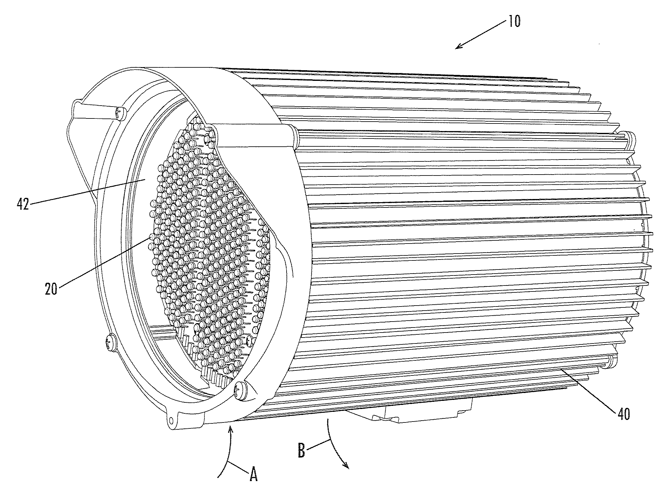
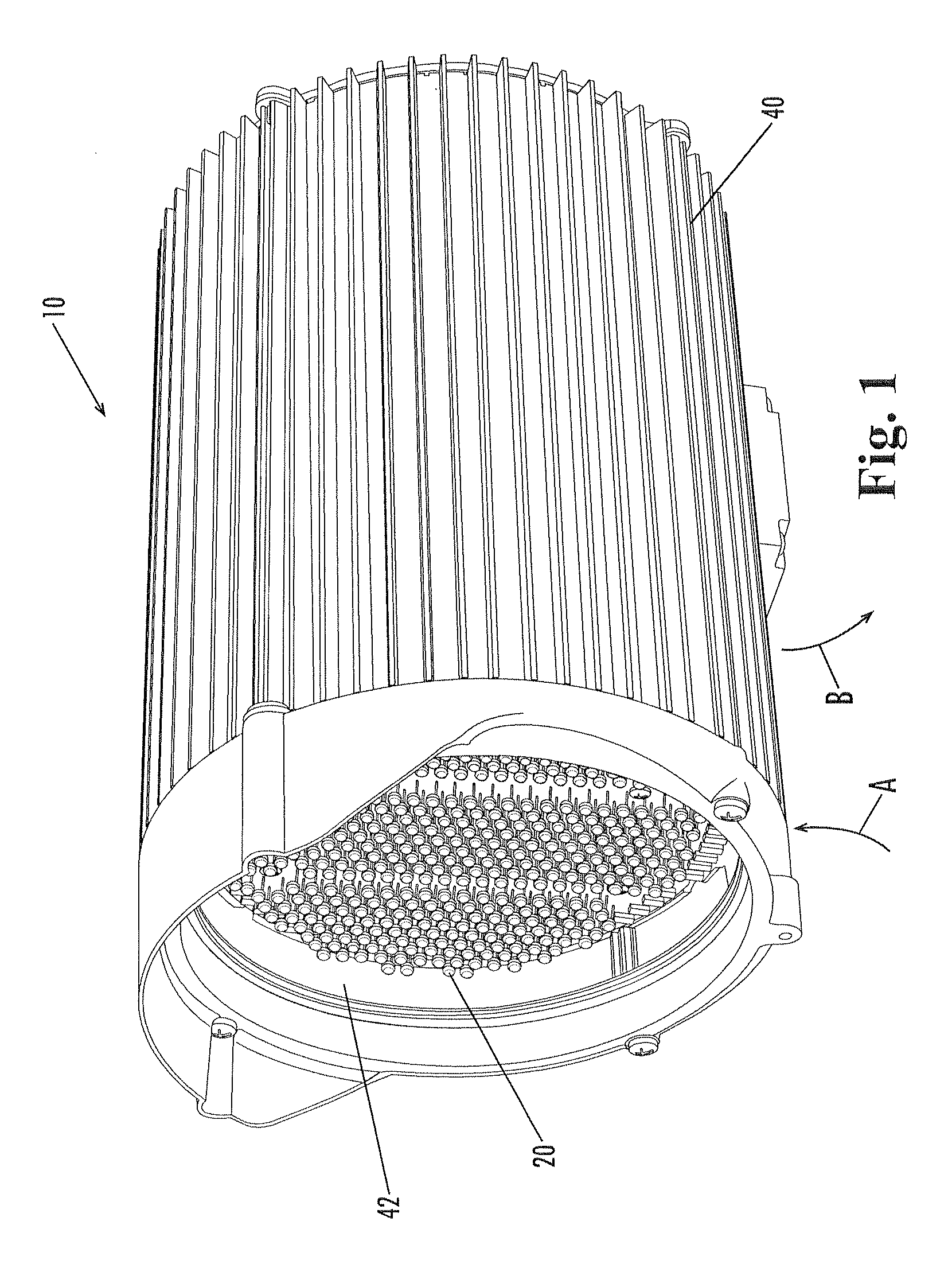
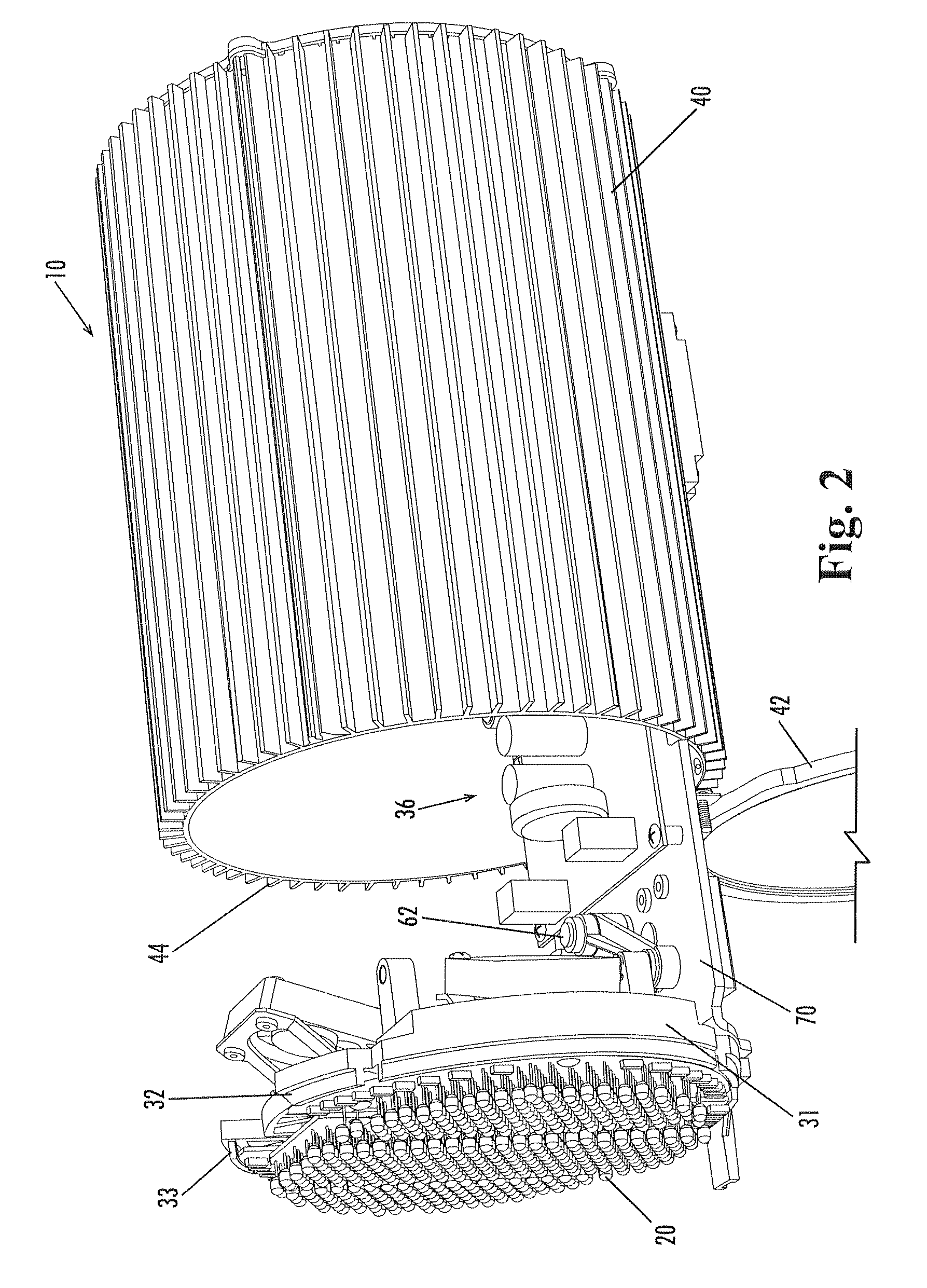
Infrared illuminator with variable beam angle

a technology of infrared illuminator and beam angle, which is applied in the field of infrared illuminator with variable beam angle, can solve the problems of inefficiency and/or less than optimal illumination performance, and inability to meet the needs of lighting support devices

Inactive Publication Date: 2008-06-26
VIDEOLARM
View PDF38 Cites 99 Cited by
  • Summary
  • Abstract
  • Description
  • Claims
  • Application Information

AI Technical Summary

Benefits of technology

[0009]In still another aspect, the present invention is an illuminator including a first light source, a second light source, and a control mechanism whereby the second light source is positionally adjustable relative to the first l...

Problems solved by technology

Known infrared illuminators, however, are not as versatile as might be desired, and often require a user to purchase and install different types of illuminators to provide different illumination field widths and / or ranges to satisfy a particular application.
This is often not feasible or practical and can lead to inefficiencies and / or less than optimal illumination performance.
Also, distributors, sellers and / or installers may need to stock multiple types of illuminator units for applications requiring different fields and / or ranges of illumination, which can result in availability problems and inefficiencies.

Method used


Image

  • Infrared illuminator with variable beam angle
  • Infrared illuminator with variable beam angle
  • Infrared illuminator with variable beam angle

Examples


Embodiment Construction

[0023]The present invention may be understood more readily by reference to the following detailed description of the invention taken in connection with the accompanying drawing figures, which form a part of this disclosure. It is to be understood that this invention is not limited to the specific devices, methods, conditions or parameters described and / or shown herein, and that the terminology used herein is for the purpose of describing particular embodiments by way of example only and is not intended to be limiting of the claimed invention. Also, as used in the specification including the appended claims, the singular forms “a,”“an,” and “the” include the plural, and reference to a particular numerical value includes at least that particular value, unless the context clearly dictates otherwise. Ranges may be expressed herein as from “about” or “approximately” one particular value and / or to “about” or “approximately” another particular value. When such a range is expressed, another...


PUM


Abstract

An infrared surveillance system including a first member with a first infrared light source mounted thereto, and a second member with a second infrared light source mounted thereto. The second member is positionally adjustable relative to the first member. The surveillance system also includes an infrared camera in operative communication with at least the second member to vary an illumination field provided by the first and second light sources depending on the camera's field of view. The surveillance system also includes at least one controller for varying the output intensity of the light sources.

Description

CROSS-REFERENCE TO RELATED APPLICATION[0001]This application is a continuation-in-part of U.S. Non-Provisional patent application Ser. No. 11 / 933,599, filed Nov. 1, 2007, which claims the priority benefit of U.S. Provisional Patent Application Ser. No. 60 / 863,912, filed Nov. 1, 2006. These applications are hereby incorporated herein by reference in their entireties for all purposes.TECHNICAL FIELD[0002]The present invention relates generally to illuminators and surveillance systems, and more particularly, to a variable beam angle infrared illuminator used in conjunction with infrared image capturing and surveillance technology.BACKGROUND OF THE INVENTION[0003]Infrared cameras are able to acquire images in low or almost no light circumstances. Therefore, infrared cameras have long been used in the fields of night-vision systems, surveillance, military operations, and wildlife photography. In many instances, an infrared illuminator is used in combination with such cameras to project i...

Claims


Application Information

Patent Timeline
IPC IPC(8): H04N7/18F21V21/14
CPCG08B13/19619G08B13/19626H04N5/33H04N5/2256G08B13/19636H04N23/56
Inventor EREL, BULENTHARDEN, CHRIS W.HUNT, VIRGIL L.SCHNEIDER, PETER G.PAGANO, RAYMOND V.PFAFFENBERGER, JAMES L.
Owner VIDEOLARM
Learn More