Arrangement and interface for RF ablation system with acoustic feedback

a technology of acoustic feedback and an arrangement of electrodes, applied in the direction of catheters, applications, ultrasonic/sonic/infrasonic diagnostics, etc., can solve the problems of significant loss of electrode tip metal for rf (radiofrequency, undesirably large tip size to accommodate the two transducers, etc., to reduce the chance of popping

Active Publication Date: 2013-10-01
ST JUDE MEDICAL
View PDF14 Cites 40 Cited by
  • Summary
  • Abstract
  • Description
  • Claims
  • Application Information

AI Technical Summary

Benefits of technology

[0009]In some embodiments, processing the transducer detection information by the transducer detection information processing module comprises identifying activity indicative of prepopping. The ablation power control module is configured, in response to the identified activity indicative of prepopping, to adjust at least one of an ablation power, a duty-cycle or ramp-rate, and an ablation irrigant flow rate to reduce a chance for popping. The system further comprises a user interface to receive input from a user to be displayed or to be used for executing the one or more modules by the processor. Only one pulse-echo ultrasonic transducer is provided in the catheter. The system further comprises a manipulation mechanism to manipulate the distal portion of the catheter body in movement including rotation of at least the distal portion of the catheter around the longitudinal axis. The one or more modules include a manipulation mechanism control module to control the manipulation mechanism to rotate at least the distal portion of the catheter body.

Problems solved by technology

This requires the use of dual transducers in an ablation instrument such as a catheter, resulting in a considerable expense and a significant loss of electrode tip metal for RF (radiofrequency) ablation or the like.
Such an approach leads to an undesirably larger tip size to accommodate the two transducers or to poorer performing smaller (thinner) acoustic standoffs and / or backers for the dual transducers.

Method used


Image

  • Arrangement and interface for RF ablation system with acoustic feedback
  • Arrangement and interface for RF ablation system with acoustic feedback
  • Arrangement and interface for RF ablation system with acoustic feedback

Examples


Embodiment Construction

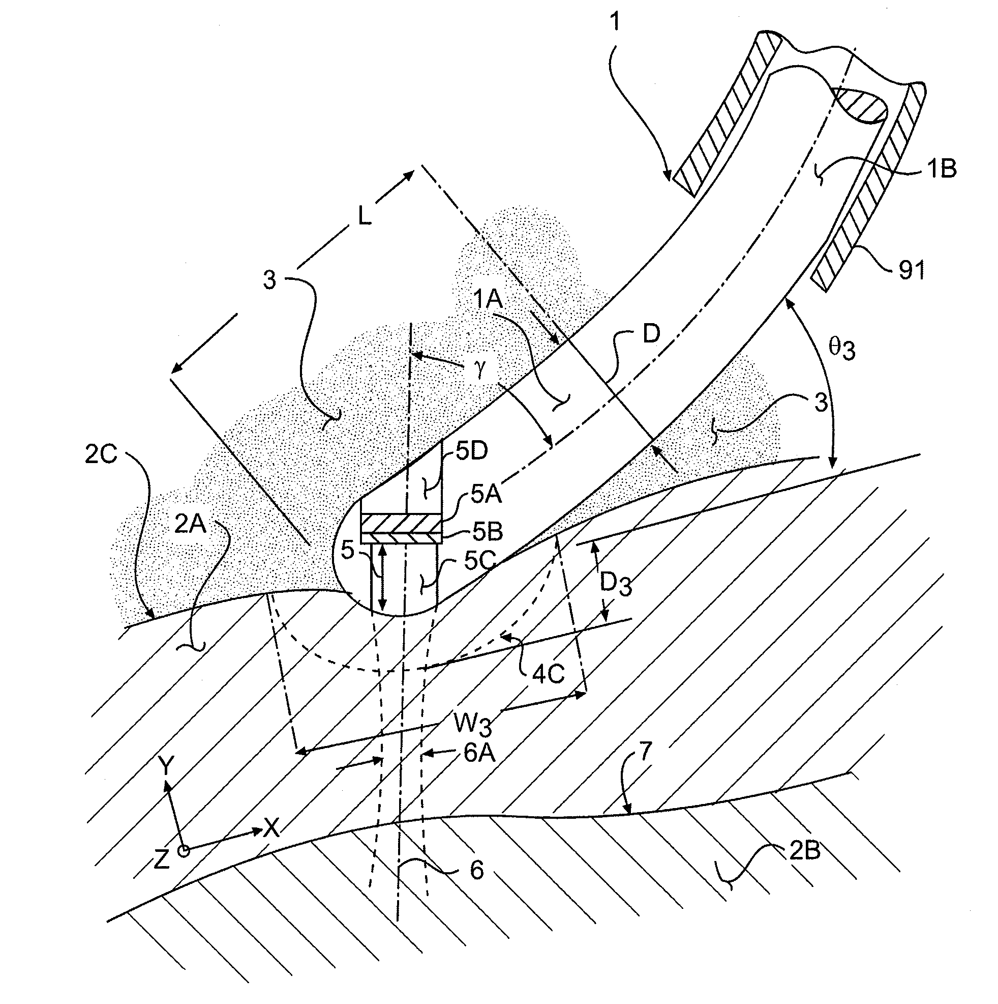
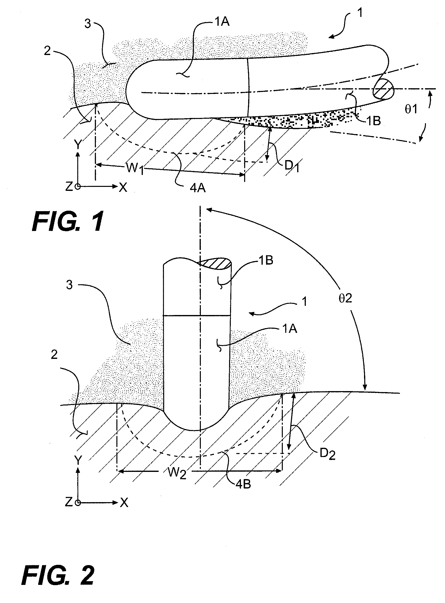
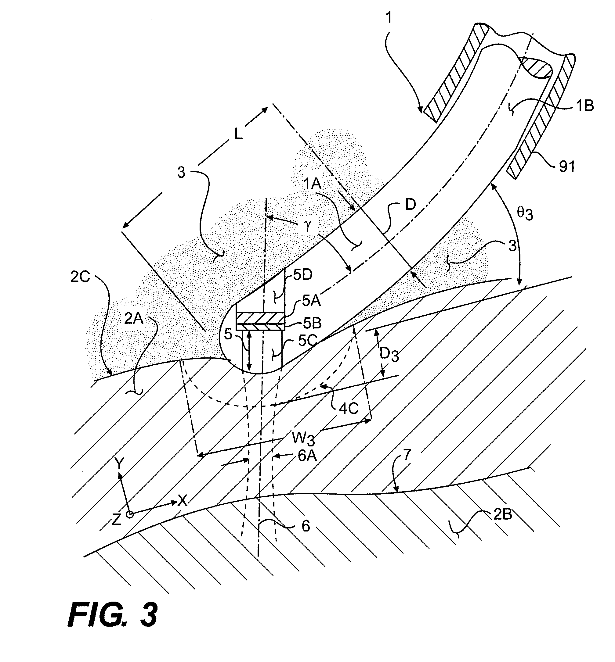
[0025]In the following detailed description of the invention, reference is made to the accompanying drawings which form a part of the disclosure, and in which are shown by way of illustration, and not of limitation, exemplary embodiments by which the invention may be practiced. In the drawings, like numerals describe substantially similar components throughout the several views. Further, it should be noted that while the detailed description provides various exemplary embodiments, as described below and as illustrated in the drawings, the present invention is not limited to the embodiments described and illustrated herein, but can extend to other embodiments, as would be known or as would become known to those skilled in the art. Reference in the specification to “one embodiment,”“this embodiment,” or “these embodiments” means that a particular feature, structure, or characteristic described in connection with the embodiment is included in at least one embodiment of the invention, a...


PUM


Abstract

A system for ablation with acoustic feedback comprises: a catheter which includes an elongated catheter body; at least one ablation element to ablate a targeted tissue region; and a pulse-echo ultrasonic transducer arranged to emit and receive an acoustic beam along a centroid in a beam direction, at a transducer beam angle of between about 30 degrees and about 60 degrees relative to a distal direction of the longitudinal axis at a location of intersection between the longitudinal axis and the beam direction of the centroid of the acoustic beam of the ultrasonic transducer, wherein the transducer transmits and receives acoustic pulses to provide lesion information in the targeted tissue region; an ablation power subsystem; an ultrasonic transmit and receive subsystem to operate the ultrasonic transducer; a control subsystem to control operation of the ablation power subsystem and the ultrasonic transmit and receive subsystem; and a display.

Description

RELATED APPLICATIONS[0001]This application is a continuation-in-part of U.S. patent application Ser. No. 13 / 086,605, filed Apr. 14, 2011. This application is also a continuation-in-part of U.S. patent application Ser. No. 13 / 113,170, filed May 23, 2011. The entire disclosures of these applications are incorporated herein by reference.BACKGROUND OF THE INVENTION[0002]The present invention relates generally to ablation devices and, more specifically, to a combination catheter for forward and side lesioning with acoustic or ultrasonic lesion feedback capability.[0003]Current industry R&D in ultrasonic lesion feedback focuses on transducers that look out from the ablation electrode tip both forwardly and sideways. This requires the use of dual transducers in an ablation instrument such as a catheter, resulting in a considerable expense and a significant loss of electrode tip metal for RF (radiofrequency) ablation or the like. Such an approach leads to an undesirably larger tip size to a...

Claims


Application Information

Patent Timeline
Patent Type & Authority Patents(United States)
IPC IPC(8): A61B8/00
CPCA61B8/0858A61B8/12A61B8/5223A61B18/1492A61B8/445A61B2018/00357A61B2018/00577A61B2018/00738A61B2019/2219A61B2019/528A61B2090/3784A61B2034/303G16H50/30
Inventor SLIWA, JOHNNGUYEN, THO HOANGMA, ZHENYIMORSE, STEPHEN
Owner ST JUDE MEDICAL
Why Eureka
Try Eureka