Hidden ultrasonic transducer with beam angle control for non-contact target detection systems

a technology of hidden ultrasonic transducers and beam angle control, which is applied in the direction of mechanical vibration separation, instruments, measurement devices, etc., can solve the problem of unsuitable visible positioning of the transducer on the vehicl

Active Publication Date: 2010-08-19
MASSA PRODS CORP
View PDF7 Cites 37 Cited by
  • Summary
  • Abstract
  • Description
  • Claims
  • Application Information

AI Technical Summary

Benefits of technology

[0009]An additional object of this invention is to provide mounting means to allow the transducer to be mechanically held in place behind the continuous sheet of material.

Problems solved by technology

However, in certain cases, such as sensors used in the automotive industry, having transducers mounted onto the vehicle visibly is not desirable because it interferes with the look and style of the car.

Method used


Image

  • Hidden ultrasonic transducer with beam angle control for non-contact target detection systems
  • Hidden ultrasonic transducer with beam angle control for non-contact target detection systems
  • Hidden ultrasonic transducer with beam angle control for non-contact target detection systems

Examples


Embodiment Construction

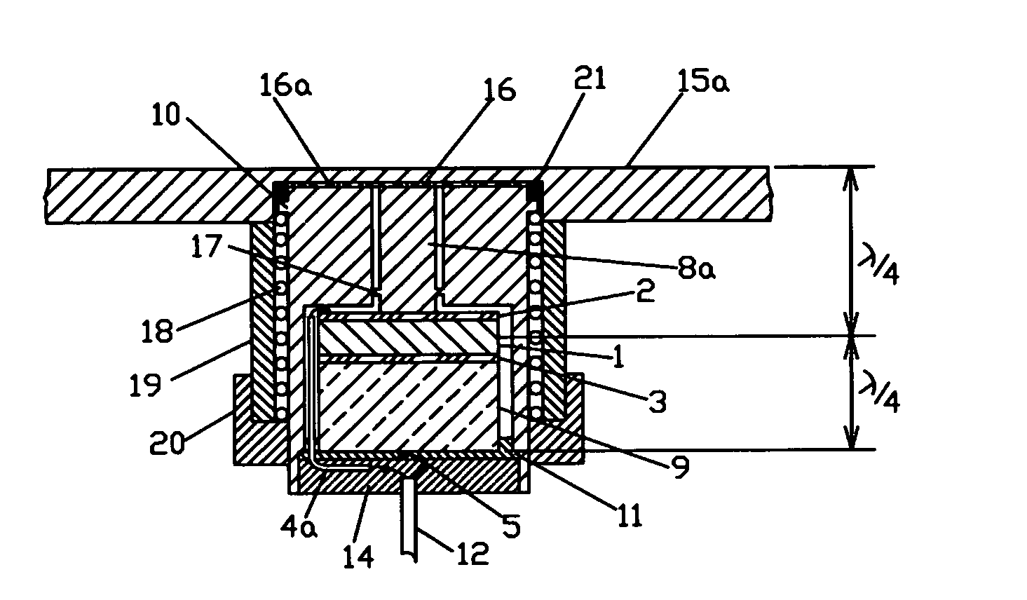
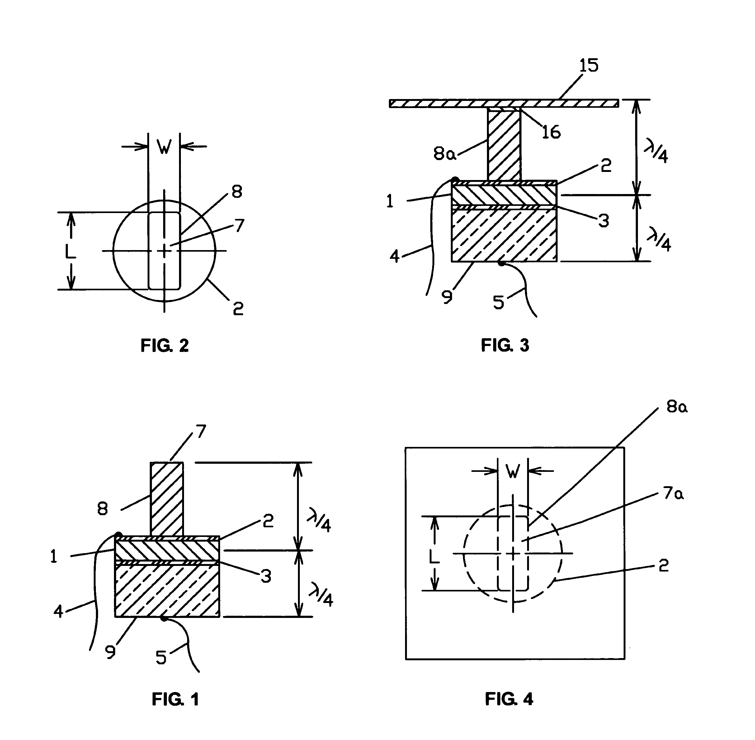
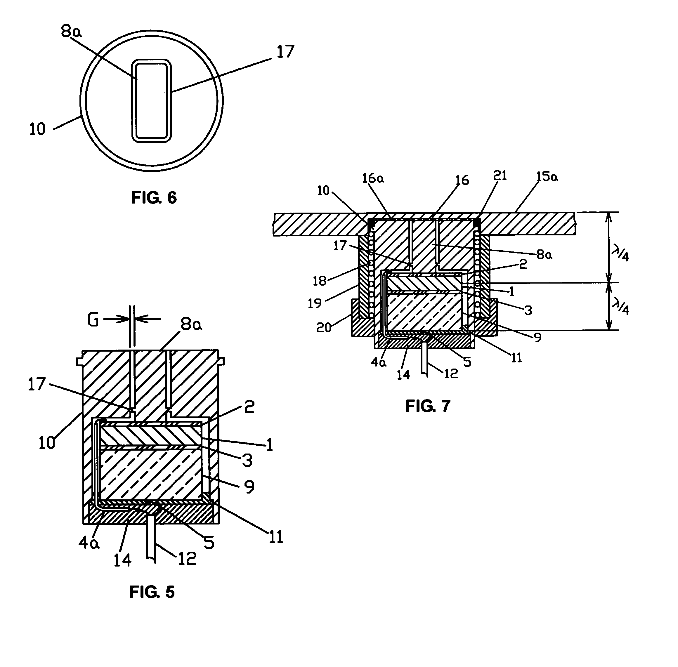
[0022]Referring more particularly to the figures, FIG. 1 shows a schematic cross-sectional of a half wavelength resonant element of a transducer that will produce a fan shaped radiation beam. This is similar to the half wavelength resonant element shown in FIG. 6 of the co-pending application. A half wavelength resonator such as shown in FIG. 5 or FIG. 8 of the co-pending application, or a quarter wavelength resonator such as shown in FIG. 1 or FIG. 2 of the co-pending application could also be used in the resonating element in FIG. 1. FIG. 2 shows a top view of the structure of FIG. 1. The transduction material consists of a thin piezoelectric ceramic disc 1, which may be any one of the well known polarized ceramic materials such as, for example, lead-zirconate-titanate or barium titanate. The flat surfaces of the ceramic disc 1 are coated with metallic electrodes 2 and 3. They could be silver, electroless nickel, or some other material as is well known in the art.

[0023]The thin ce...


PUM


Abstract

An ultrasonic transducer utilizes a unique forward acoustic transmission line comprised of a composite structure partially consisting of a portion of a continuous smooth sheet of material, such as an automobile bumper, from which the acoustic beam is emitted. This makes it invisible to sight, thus allowing for an improved object detection system in which the sensors cannot be seen, so that they do not interfere with the smooth lines that were designed into the surface of the object or vehicle onto which they are mounted. This is a significant improvement for applications where the look and style of the surface of the platform is important, such as in automotive park assist systems.

Description

CROSS REFERENCE TO RELATED APPLICATIONS[0001]Not ApplicableSTATEMENT REGARDING FEDERALLY SPONSORED RESEARCH OR DEVELOPMENT[0002]Not ApplicableREFERENCE TO SEQUENCE LISTING, A TABLE, OR A COMPUTER PROGRAM LISTING COMPACT DISC APPENDIX[0003]Not ApplicableBACKGROUND OF THE INVENTION[0004]This invention is a continuation-in-part of the invention described in my co-pending application Ser. No. 12 / 460,790 that was filed as a non-provisional application on Jul. 24, 2009, and is concerned with further improvements in the design of electroacoustic transducers for transmitting or receiving sound in a fluid medium, as described in said co-pending application. Although not limited to the ultrasonic frequency region, this improvement in the performance characteristics of electroacoustic transducers is primarily to be used in the ultrasonic frequency region in a gaseous medium.[0005]The teachings of this invention can be used by one skilled in the art in a wide variety of transducer designs using...

Claims


Application Information

Patent Timeline
Patent Type & Authority Applications(United States)
IPC IPC(8): G01S15/04B06B1/06
CPCG01F1/662G10K9/22G10K9/122G01F1/667
Inventor MASSA, DONALD PATRICK
Owner MASSA PRODS CORP
Why Eureka
Try Eureka