Methods and Systems for Guiding Clinical Radiotherapy Setups

a technology of clinical radiotherapy and setup, applied in the field of methods and systems for improving setup in radiotherapy, can solve the problems of limiting treatment to the primary lumpectomy site, unable to take into account the actual position of the cavity, cumbersome gantry and collimator to properly orient the patient, etc., and achieve the effect of facilitating the determination of the desired gantry

Active Publication Date: 2010-01-14
ELEKTA AB
View PDF100 Cites 42 Cited by
  • Summary
  • Abstract
  • Description
  • Claims
  • Application Information

AI Technical Summary

Benefits of technology

[0010]Embodiments of the present invention provide systems and methods for incorporating internal and external anatomical features of a patient and radiation-beam parameters into radiation-treatment treatment and/or planning regimens. A tracked tool or instrument may

Problems solved by technology

The boost sessions are typically delivered with an electron beam, which limits treatment to the primary lumpectomy site.
One weakness of clinical planning is that the actual position of the cavity is not explicitly taken into account.
These adjustments are often necessary because it is difficult to reposition the breast in exa

Method used


Image

  • Methods and Systems for Guiding Clinical Radiotherapy Setups
  • Methods and Systems for Guiding Clinical Radiotherapy Setups
  • Methods and Systems for Guiding Clinical Radiotherapy Setups

Examples


Embodiment Construction

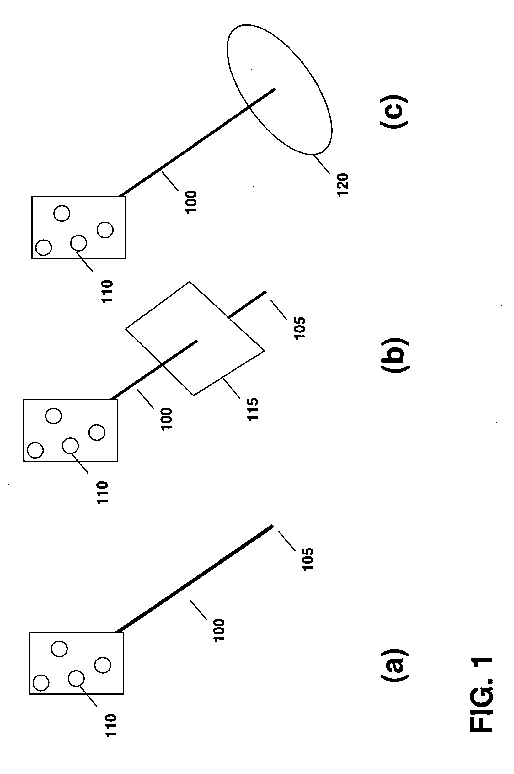
[0027]FIG. 1 illustrates an exemplary wand tool in accordance with various embodiments of the invention. As shown in FIG. 1(a), the wand has a shaft 100 and a tip 105 that is preferably well-defined, for example, as a sharp, blunt or ball tip. In some embodiments, an array of markers 110 are affixed to the pointer. The markers 110 can be detected by a conventional optical tracker in real-time. The markers can be tracked either individually or as a preconfigured shape configuration, which defines a position and orientation in space. The position and orientation are calibrated so that the position of the tip 105, the orientation of the shaft 100, long-axis rotation and shaft rotation about its long axis, can be calculated at any given time as the wand is moved. Examples of markers include passive infrared reflectors, or active infrared emitters, which can be tracked by an optical camera or cameras such as the POLARIS family of cameras. Other types of trackers, such as magnetic or radi...


PUM


Abstract

Radiation beam parameters are determined by manipulating a tool about a patient in order to determine a desired beam entry point and/or beam angle. In certain embodiments, a visual representation of the beam may be displayed along with images of internal and external anatomical features of the patient, and used to determine couch and/or gantry manipulation parameters to move the patient into a desired position with respect to a treatment delivery device.

Description

CROSS-REFERENCE TO RELATED APPLICATIONS[0001]This application claims priority to and the benefits of U.S. provisional patent application Ser. No. 61 / 058,049, filed on Jun. 2, 2008, the entire disclosure of which is incorporated herein by referenceFIELD OF THE INVENTION[0002]This invention relates generally to methods and systems for improving setups in radiotherapy.BACKGROUND OF THE INVENTION[0003]External-beam radiotherapy for breast cancer is typically provided using opposing tangential fields, which deliver a uniform dose to the entire affected breast. The primary treatment is given over a number of sessions, and is often followed by additional boost sessions. The boost sessions are typically delivered with an electron beam, which limits treatment to the primary lumpectomy site.[0004]Unlike photons, the intensities of which decrease exponentially as the photons travel through a patient, an electron beam deposits most of its energy dose within a fixed, finite range based primarily...

Claims


Application Information

Patent Timeline
IPC IPC(8): A61N5/10
CPCA61B2019/507A61N2005/1059A61N5/103A61B2019/5437A61B2034/107A61B2090/3937A61N2005/1074
Inventor DUSSAULT, CHANTALLACHAINE, MARTINLODU, DANIELBONNEVILLE, MARTIN
Owner ELEKTA AB
Why Eureka
Try Eureka