Steerable radial line slot antenna
a slot antenna and radial line technology, applied in the field of antennas, can solve the problems of single polarization device, antenna does not show printing diversity, and it is difficult, if not impossible at all, to keep the phase of the converging wavelet constant, and achieves the effect of maximum sensitivity and high overall efficiency
- Summary
- Abstract
- Description
- Claims
- Application Information
AI Technical Summary
Benefits of technology
Problems solved by technology
Method used
Image
Examples
first embodiment
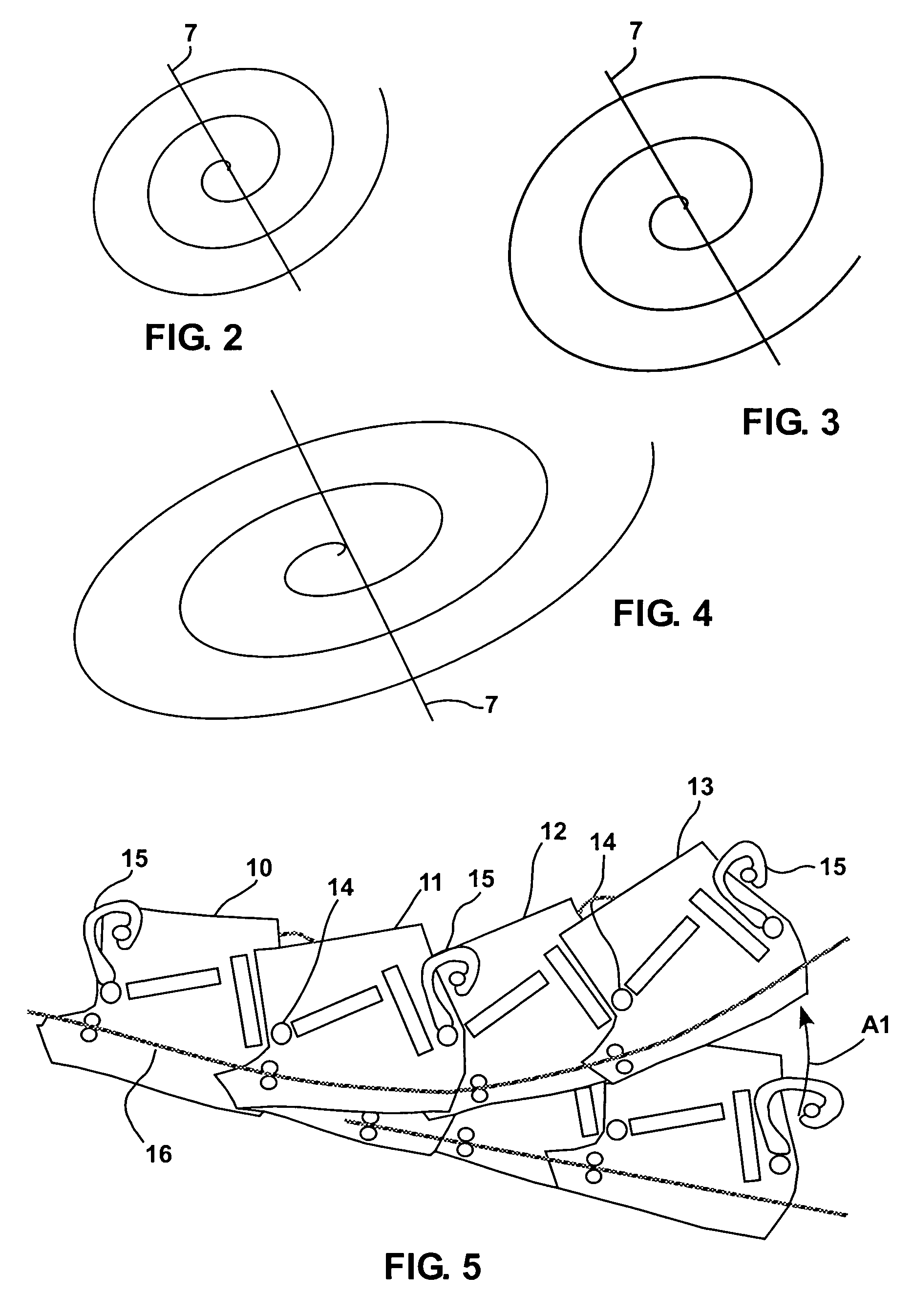
[0039]FIG. 5 shows an arrangement of slots according to the present disclosure, wherein movement along a radius is obtained. Slotted segments 10, 11, 12 and 13 are shown in two different positions, where the second position (top segments) is reached in the direction of the arrow A1 and is obtained by locally changing the pitch angle of the slot pattern which acts to change the radial position of a segment. In particular, the segments comprise hinge pivots 14 which allow each segment to be reoriented relative to an angle. Additionally, the segments comprise spring fingers 15 to provide torque control as a function of position along a length of mated segments. Motion of the segments 10–13 is obtained, for example, by an actuator (not shown) releasing or applying tension to a tensioning cable 16.
[0040]Tensioning of the cable 16 and torque inducement are obtained by means of the above discussed actuators. The actuators are usually placed at the ends of the circular or spiral sections.
[0...
second embodiment
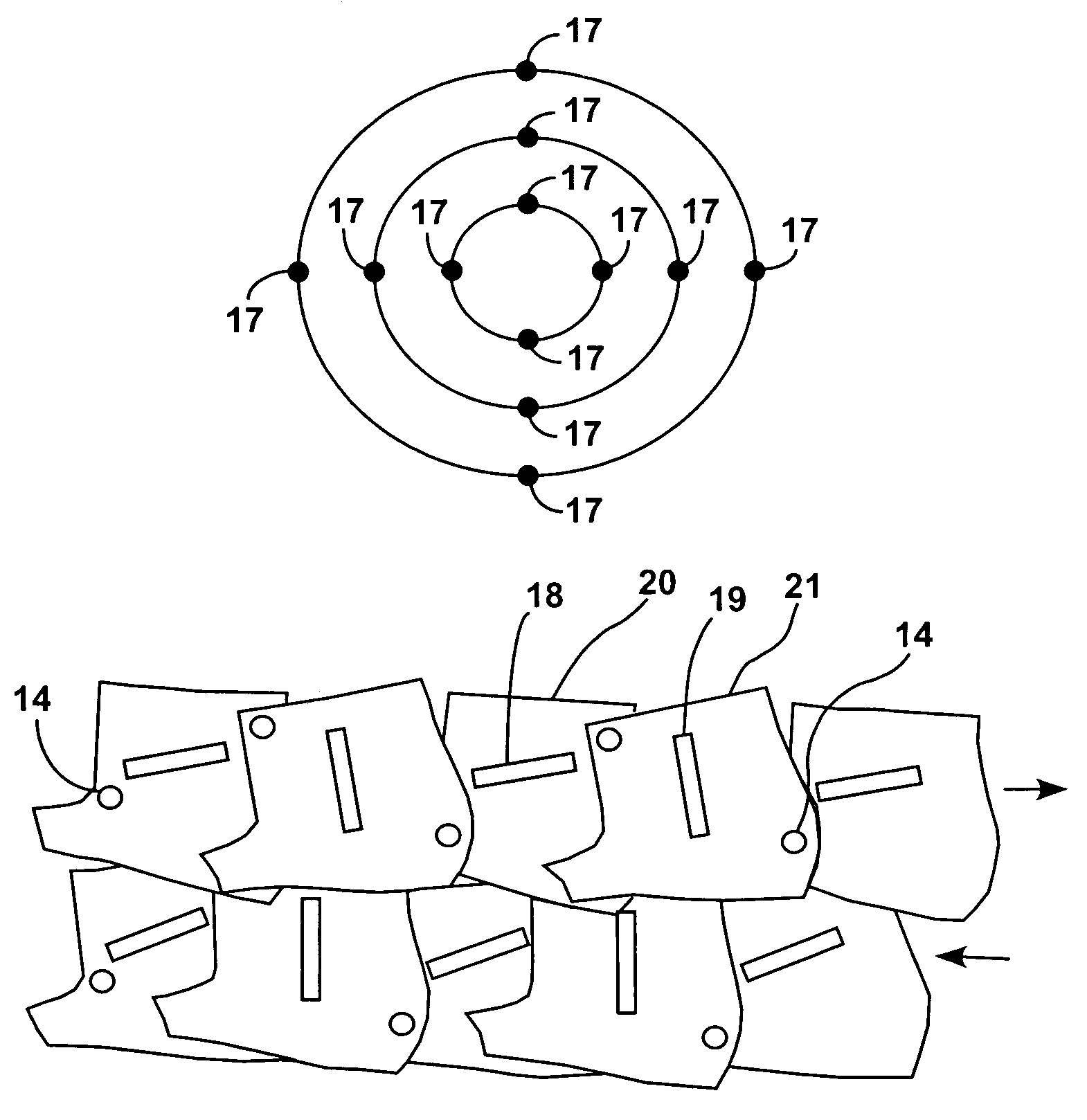
[0042]FIG. 7 shows an arrangement of slots according to the present disclosure, wherein movement is targeted towards contraction or expansion of the slot pattern. In particular, FIG. 7 shows that the distortion may be in the form of extension by offsetting the hinge positions 14. Additionally, in this embodiment, each portion 18, 19 of a T-shaped slot is contained in a different segment 20, 21, respectively.
[0043]The movement of the segments in FIGS. 5 and 7 is also obtained by means of the hinges 14. In particular, the moving slotted segments are supported by similarly constructed hinged baffles that fill in blank spaces between the slotted segments. The segments can be formed by metalized thin plastic parts. Metallization preferably extends around the dielectric element to better contact the baffles.
[0044]FIG. 8 shows slotted segments 22 and baffles 23 in a partial sectional view. Metallization is represented by a darkened peripheral side 24 of the segments 22 and 25 of the baffle...
third embodiment
[0065] a plurality of dielectric rods 48 can be provided, as shown in FIG. 16, where only a portion of those rods is shown, for the sake of clarity. The dimension of the rods 48 is much less than the wavelength of the radiation. The rods 48 are pushed inward or retracted from the bottom of the guide through a screen mesh 49. The depth of penetration determines the local phase shift. The rods 48 are inserted in pie-shaped directions according to tilt angle and direction. The small size of the rods will allow to pass the TEM mode smoothly below the cutoff frequency for the higher order modes.
PUM
 Abstract
Description
Claims
Application Information
 - R&D
- Intellectual Property
- Life Sciences
- Materials
- Tech Scout
- Unparalleled Data Quality
- Higher Quality Content
- 60% Fewer Hallucinations
Browse by: Latest US Patents, China's latest patents, Technical Efficacy Thesaurus, Application Domain, Technology Topic, Popular Technical Reports.
© 2025 PatSnap. All rights reserved.Legal|Privacy policy|Modern Slavery Act Transparency Statement|Sitemap|About US| Contact US: help@patsnap.com


