Electrostatic actuator with interdigitated electrode structure

a technology of interdigitated electrodes and actuators, which is applied in the direction of electrostatic generators/motors, instruments, electrostatic motors, etc., can solve the problems of causing no contact, causing collision of movable electrode fingers against fixed electrode fingers, and causing a small asymmetry

Inactive Publication Date: 2008-07-03
JAPAN AVIATION ELECTRONICS IND LTD
View PDF13 Cites 17 Cited by
  • Summary
  • Abstract
  • Description
  • Claims
  • Application Information

AI Technical Summary

Benefits of technology

[0016]According to the present invention, the maximum displacement of the coupling point as a function of the difference between the length of the two hinges and the distances from the anchoring points on the substrate to which one ends of the hinges are anchored to the alignment axis line

Problems solved by technology

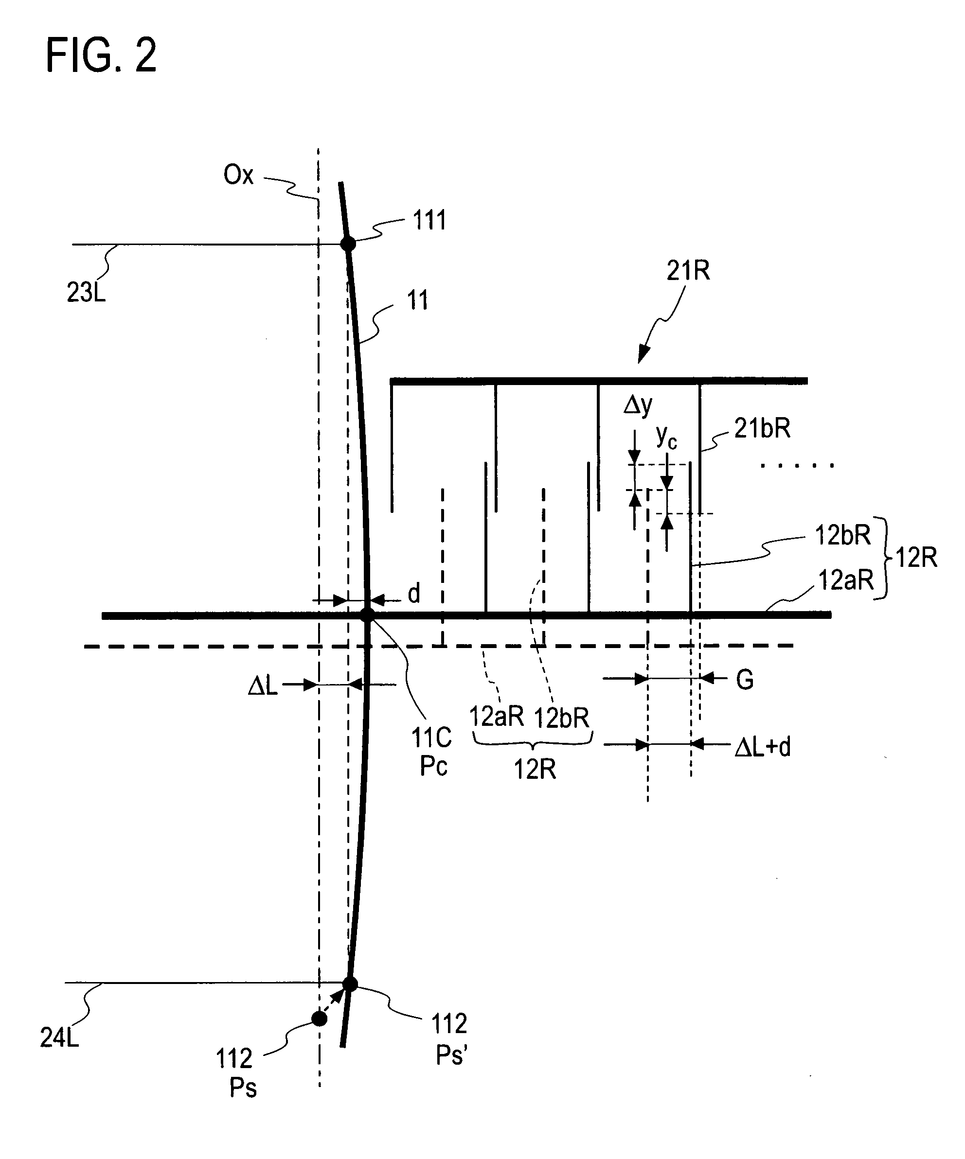
That is, it is difficult to form the hinges, fixed electrode fingers, movable electrode fingers and others strictly symmetrically about a center axis line of the movable rod in fabricating the electrostatic actuator and a very slight asymmetry is produced even when no driving voltage is applied.
When the movable electrode fingers displace even a bit in one

Method used


Image

  • Electrostatic actuator with interdigitated electrode structure
  • Electrostatic actuator with interdigitated electrode structure
  • Electrostatic actuator with interdigitated electrode structure

Examples


Embodiment Construction

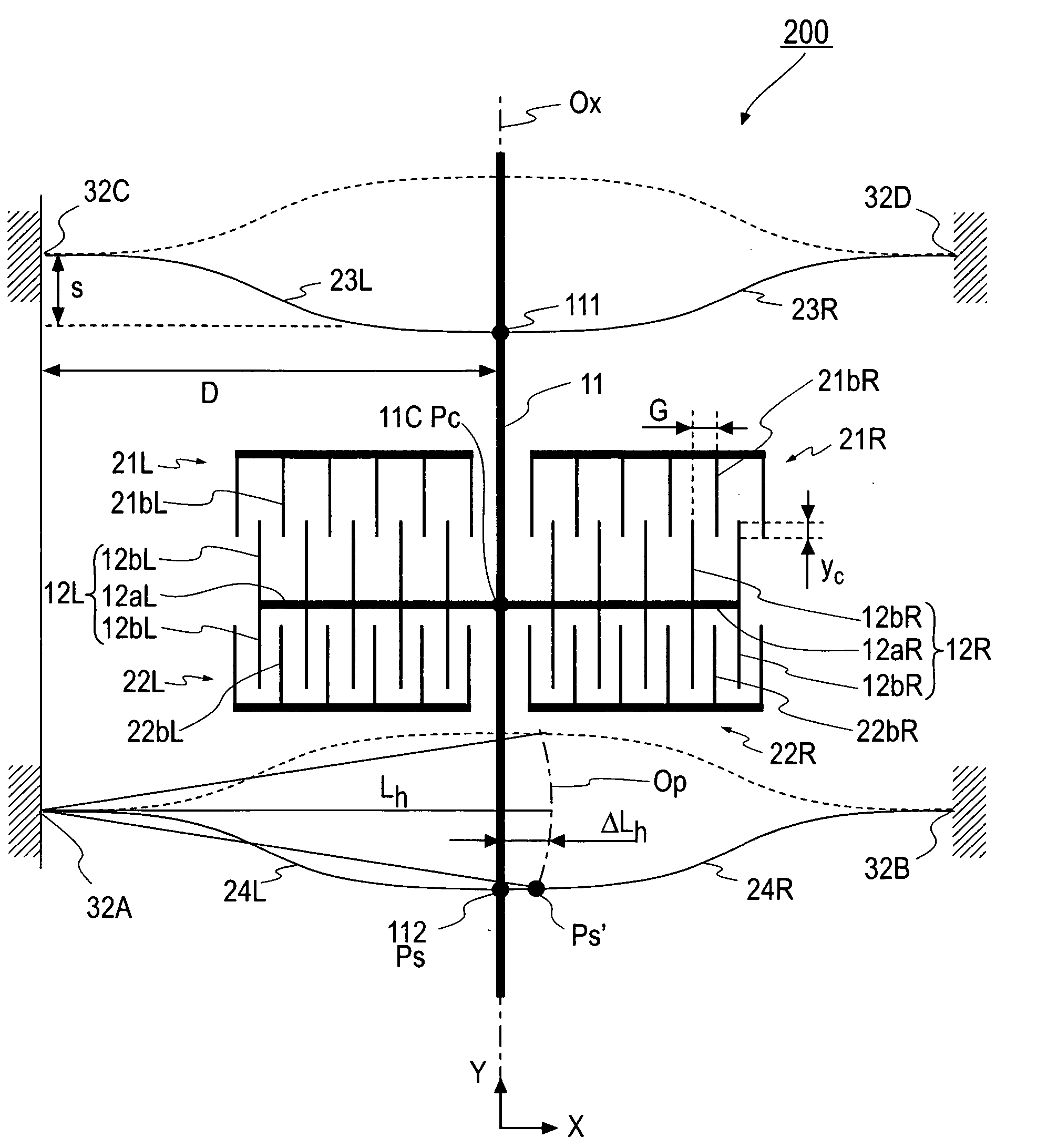
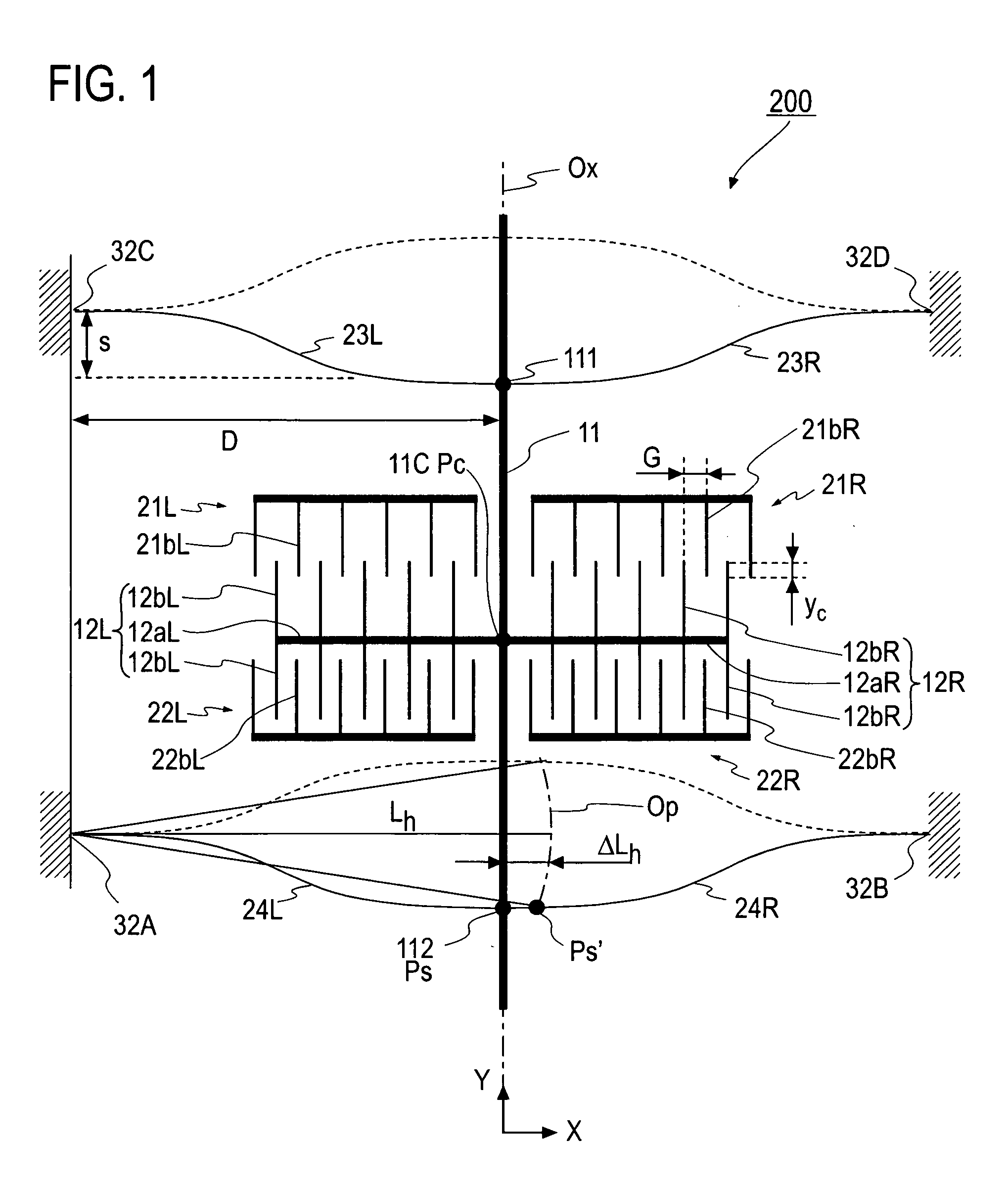
[0027]A preferred embodiment and its modifications of the invention will be explained with reference to FIGS. 1 through 7. FIG. 1 is a schematic plan view of an electrostatic actuator with an interdigitated electrode structure 200 (called simply as an actuator 200 hereinafter) according to the embodiment of the invention. A basic structure of the actuator 200 is the same as one of the actuator 100 shown in FIG. 8 and its structural elements will be explained adequately by denoting the same reference numerals to the corresponding parts.

[0028]Similarly to the actuator 100 shown in FIG. 8, the actuator 200 is formed integrally with a substrate made from a silicon wafer by implementing anisotropic etching. A movable rod 11 is disposed on an alignment axis line Ox in a stable state. Each one end of hinges 23R, 23L, 24R and 24L disposed by two each on the both sides of the movable rod 11 is anchored to supporting points 111 and 112 on the movable rod 11 and another end of the hinges 23R, ...


PUM


Abstract

There is provided an electrostatic actuator with the interdigitated electrode structure comprising a movable rod 11 disposed in parallel with an alignment axis line Ox predetermined on a substrate; a movable interdigitated electrode 12 fixed on the both sides of a coupling point 11C on the movable rod 11 and having a plurality of movable electrode fingers 12b; fixed interdigitated electrodes 21, 22 fixed to the substrate and having a plurality of fixed electrode fingers 21b, 22b; and four hinges 23, 24 whose one ends are anchored respectively to the movable rod and the other ends are anchored to anchoring points 32A-32D of the substrate. Lengths of those hinges are longer than distances from anchoring points to the alignment axis line and a displacement Lc of a coupling point 11C in a direction orthogonal to the alignment axis line is reduced to be smaller than a distance between the respective movable electrode fingers and the closest fixed electrode finger.

Description

BACKGROUND OF THE INVENTION[0001]1. Field of the Invention[0002]The present invention relates to an electrostatic actuator with an interdigitated electrode structure for use in an optical device for switching an optical path or adjusting a quantity of light coupled to each incident port by inserting / extracting a mirror into / out of an optical path.[0003]2. Description of the Related Art[0004]FIG. 8 shows a structure of a MEMS (Micro Electro Mechanical Systems) optical switch disclosed in Japanese Patent Application Laid-Open No. 2005-37885 as an exemplary prior art structure of an optical device of this sort using the electrostatic actuator with the interdigitated electrode structure.[0005]Four fiber grooves 1A, 1B, 1C and 1D are formed into a shape of a cross by being coupled from each other at each one end on an upper face 20u of a substrate 20 made from a silicon wafer for example. The four optical fibers 41A, 41B, 41C and 41D are disposed within the corresponding fiber grooves 1A...

Claims


Application Information

Patent Timeline
IPC IPC(8): H02N1/00
CPCG02B6/3514G02B6/3566H02N1/008G02B6/358G02B6/3584G02B6/357
Inventor KATO, YOSHICHIKAMORI, KEIICHI
Owner JAPAN AVIATION ELECTRONICS IND LTD
Why Eureka
Try Eureka