Vibration damping system for an engine mounted on a vehicle

Active Publication Date: 2005-11-01
KUBOTA LTD
View PDF15 Cites 14 Cited by
  • Summary
  • Abstract
  • Description
  • Claims
  • Application Information

AI Technical Summary

Benefits of technology

[0010]In a preferred embodiment of the present invention, the damping weight is supported by a weight support unit fixed at one end thereof to the crankcase of the engine. With this construction, the damping weight is maintained by the crankcase of the engine through the weight support unit. The crankcase has a stout construction compared with the cylinder head or an oil pan, and further has little possibility of causing oil leakage. As a result, the system has little chance of adversely affecting the engine, but maintains the damping weight reliably to allow the damping weight to fully perform its functions for an extended period of time.
[0011]In a further preferred embodiment of the present invention, the weight support unit includes brackets for the mounting elements. With this construction, the weight support unit for maintaining the damping weight acts also as the brackets for receiving the mounting elements for mounting the engine on the vehicle body. This realizes a simplified construction and reduced cost by reducing the number of parts.
[0012]In a still further preferred embodiment of t

Problems solved by technology

However, such a construction does not positively restrict the vibrations of the engine per se, and thus has no effect for restraining airborne noise produced by the engine vibrations.
To this end, active damping systems have begun to be proposed, but such systems still have a serious problem of large-scale construction and control as well as increased cost.
Further, the vibrations of the engine

Method used


Image

  • Vibration damping system for an engine mounted on a vehicle
  • Vibration damping system for an engine mounted on a vehicle
  • Vibration damping system for an engine mounted on a vehicle

Examples


Example

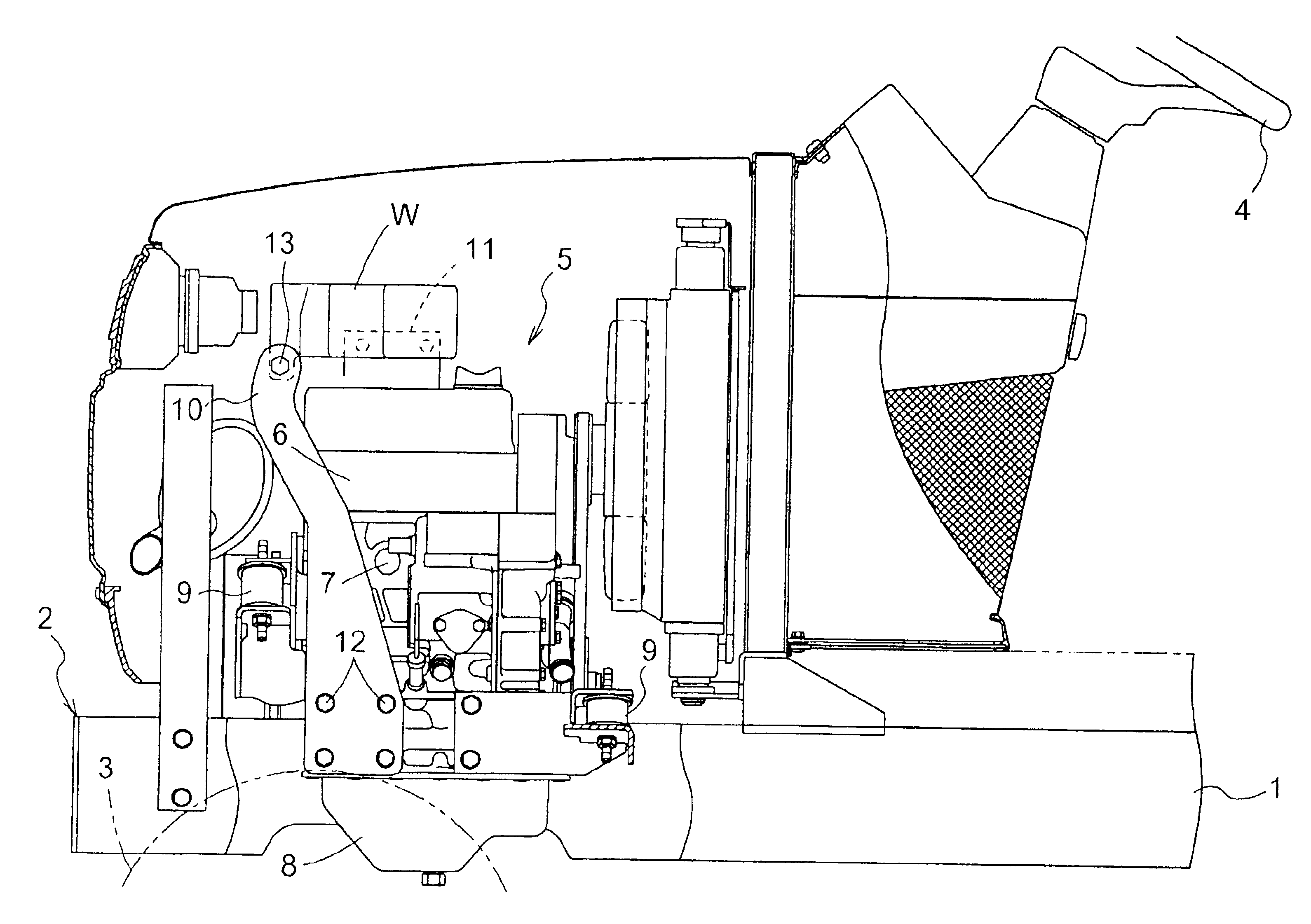
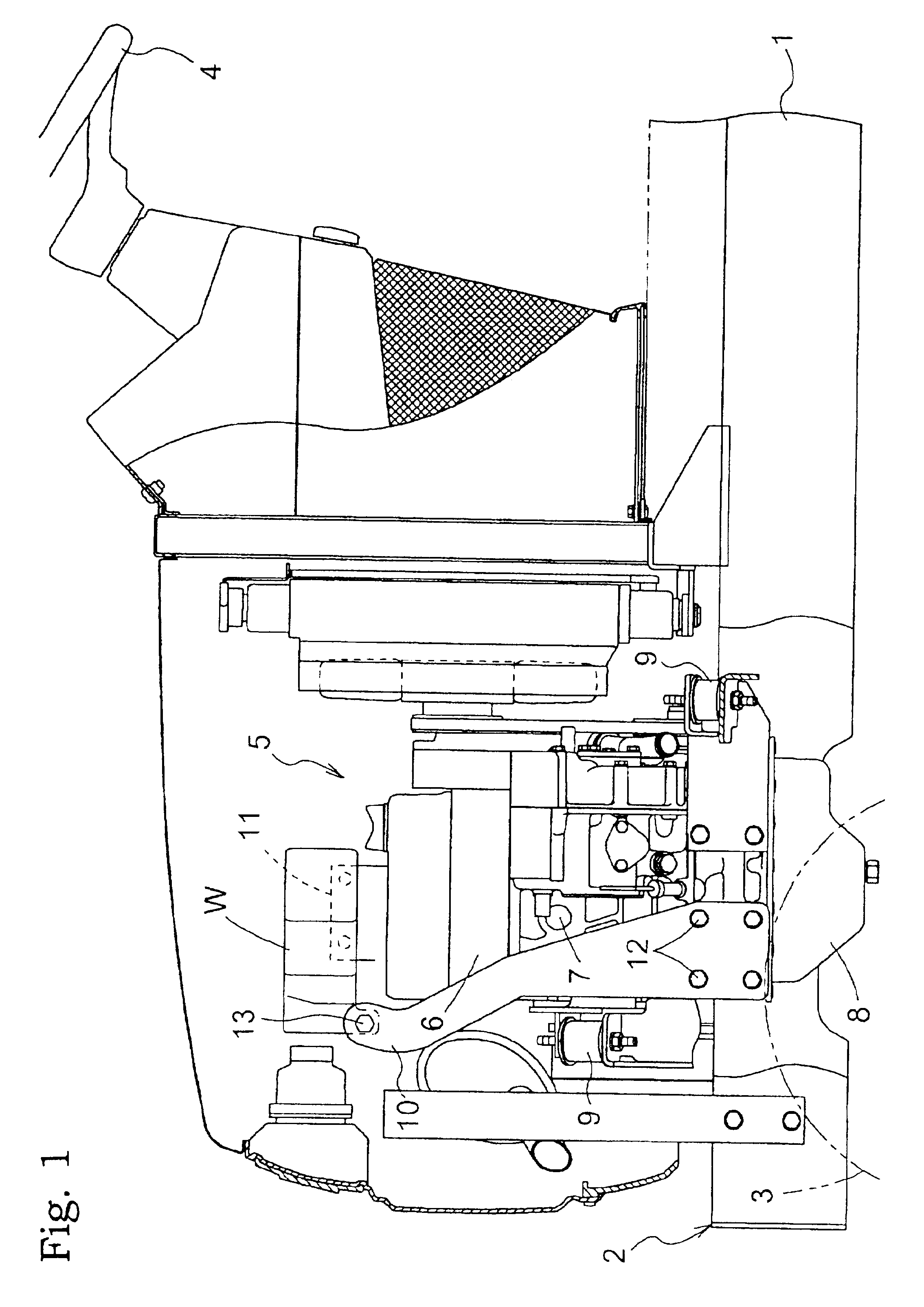
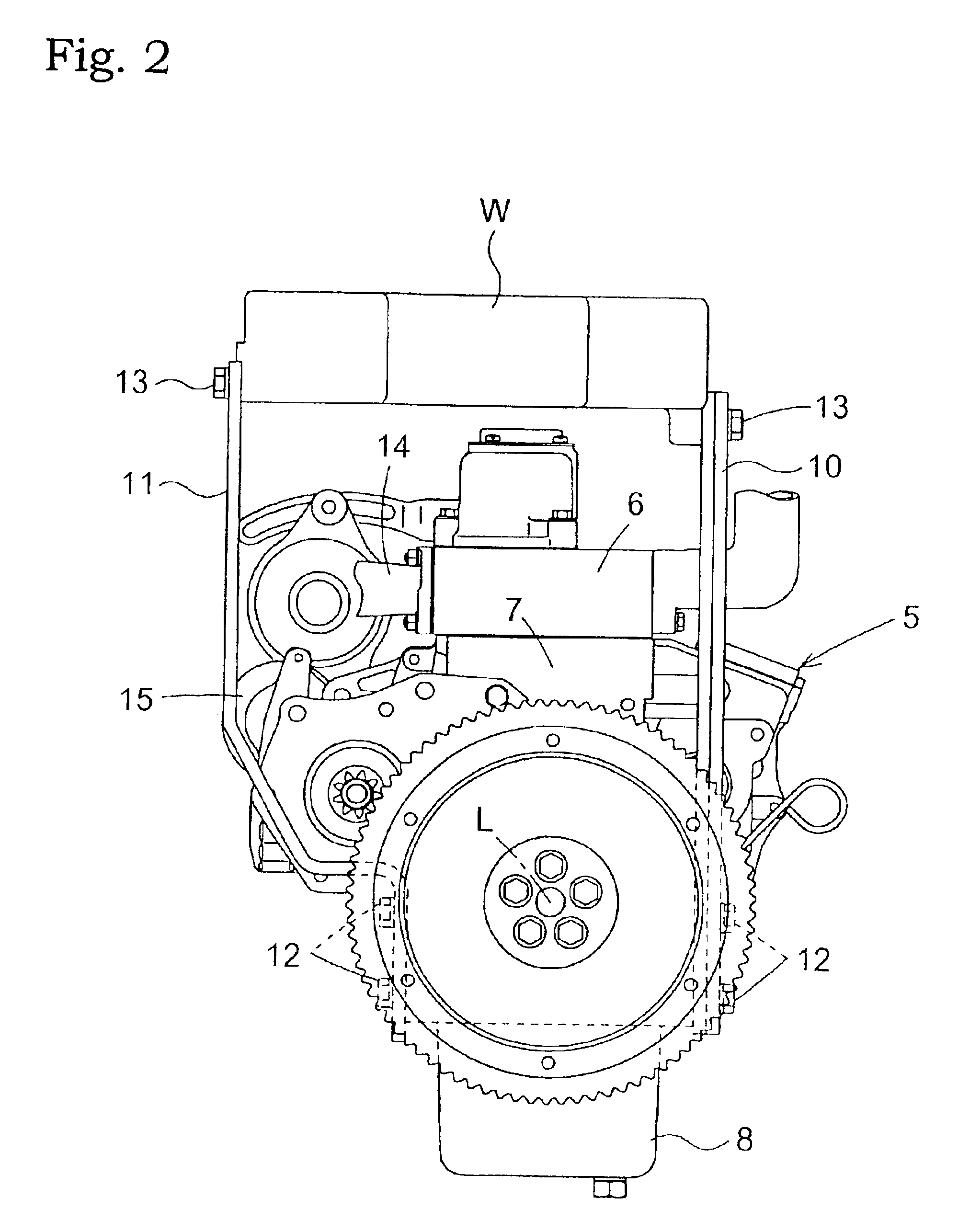
[0028]In a vibration damping system according to a first embodiment of the present invention, as shown in FIGS. 1 through 5, a weight support unit includes a left weight support arm (first arm) 10 formed of sheet metal and disposed at the left side of the engine 5 as viewed from the driver's seat, and a right weight support arm (second arm) 11 disposed at the right side of the engine 5. The left weight support arm 10 is attached to a left side face of the crankcase 7 through a plurality of bolts 12, and the right weight support arm 11 to a right side face of the crankcase 7 through a plurality of bolts 12.

[0029]The left weight support arm 10 extends substantially vertically upward from the left side face of the crankcase 7 to a level above the cylinder head 6. The right weight support arm 11 bends and bulges outwardly from the right side face of the crankcase 7 to extend upwardly and substantially vertically upward therefrom to a level above the cylinder head 6.

[0030]A damping weigh...

Example

[0034]A second embodiment of the vibration damping system according to the present invention will be described next. Like reference numerals are used to identify like parts which are the same as in the first embodiment and will not be described again to avoid unnecessary repetition. Thus, only the aspects different from the first embodiment will mainly be described.

[0035]According to the second embodiment, as shown in FIGS. 6 through 10, a weight support unit includes a base member 17, a left weight support arm (first arm) 10 formed of sheet metal and disposed at the left side of the engine 5 as viewed from the driver's seat, a front weight support arm 18 disposed forwardly of the engine 5, and an L-shaped right weight support arm (second arm) 19 disposed at the right side of the engine 5. The front weight support arm 18 and right weight support arm 19 are connected to the base member 17 to constitute a weight support subunit 16 together.

[0036]The left weight support arm 10 is attac...


PUM


Abstract

A vibration damping system for an engine mounted on a vehicle has mounting elements attached to frames of the vehicle, through which elements the engine is mounted on the frames, a damping weight provided outwardly of the engine, and a weight support unit fixed at one end thereof to the engine and having the damping weight attached at the other end thereof. The weight support unit includes a first arm extending along one lateral side of a vertical plane extending through an axis of a crankshaft and a second arm extending along the other lateral side of the vertical plane. The damping weight is attached to free ends of the arms. The damping weight is positioned above the cylinder head of the engine to extend transversely of the vertical plane.

Description

BACKGROUND OF THE INVENTION[0001]1. Field of the Invention[0002]The present invention relates to a vibration damping system for an engine mounted on a vehicle.[0003]2. Description of the Related Art[0004]An engine is conventionally mounted on vehicle frames through mounting elements including rubber cushions or the like as components, thereby to restrain vibrations from being transmitted from the engine to the frames. Various constructions and arrangements of the mounting elements for absorbing the vibrations have been proposed, and one example thereof is disclosed in U.S. Pat. No. 6,374,939.[0005]The mounting elements employed in the U.S. patent may, with some effect, restrain engine vibrations from being transmitted to the frames. However, such a construction does not positively restrict the vibrations of the engine per se, and thus has no effect for restraining airborne noise produced by the engine vibrations. Thus, some specific design is required to restrict the vibrations of t...

Claims


Application Information

Patent Timeline
IPC IPC(8): B60K5/12F16F15/02F16F7/10
CPCB60K5/1208F16F7/1028
Inventor OSHIMA, HIROSHIOSUGA, MASASHITOMIYAMA, YOSHIOKAWABATA, HIROSHI
Owner KUBOTA LTD
Why Eureka
Try Eureka