Air conditioning system

Inactive Publication Date: 2003-09-16
DAIKIN IND LTD
View PDF16 Cites 10 Cited by
  • Summary
  • Abstract
  • Description
  • Claims
  • Application Information

AI Technical Summary

Benefits of technology

In Embodiment 4, dehumidification of the primary air is effected by the rotor member (61) having the solid adsorbent like Embodiment 1. Therefore, according to this embodiment, the effects of improving design flexibility and simplifying the construction can be obtained like Embodiment 1.
Further, since a room air is used as the primary air while an outside air is used as the secondary air, this enables not only heating but also ventilation. In this case, in the heat exchanger (30), the secondary air of an outside air cools the compressed primary air. Therefore, hot heat can be recovered from the room air

Problems solved by technology

However, since the cooling system as described above accomplishes dehumidification by using the vapor isolating membrane, the air as a working fluid for the air cycle can only be dehumidified between the compressor and the expander.
Therefore, there arises the problem that limitation of placement of such a relatively large component would incur degradation in design flexibility of the overall system.
In addition, if a seal between the compressor and the expander is insufficient, this causes leakage of the compresse

Method used


Image

  • Air conditioning system
  • Air conditioning system
  • Air conditioning system

Examples


embodiment 1

Effects of Embodiment 1

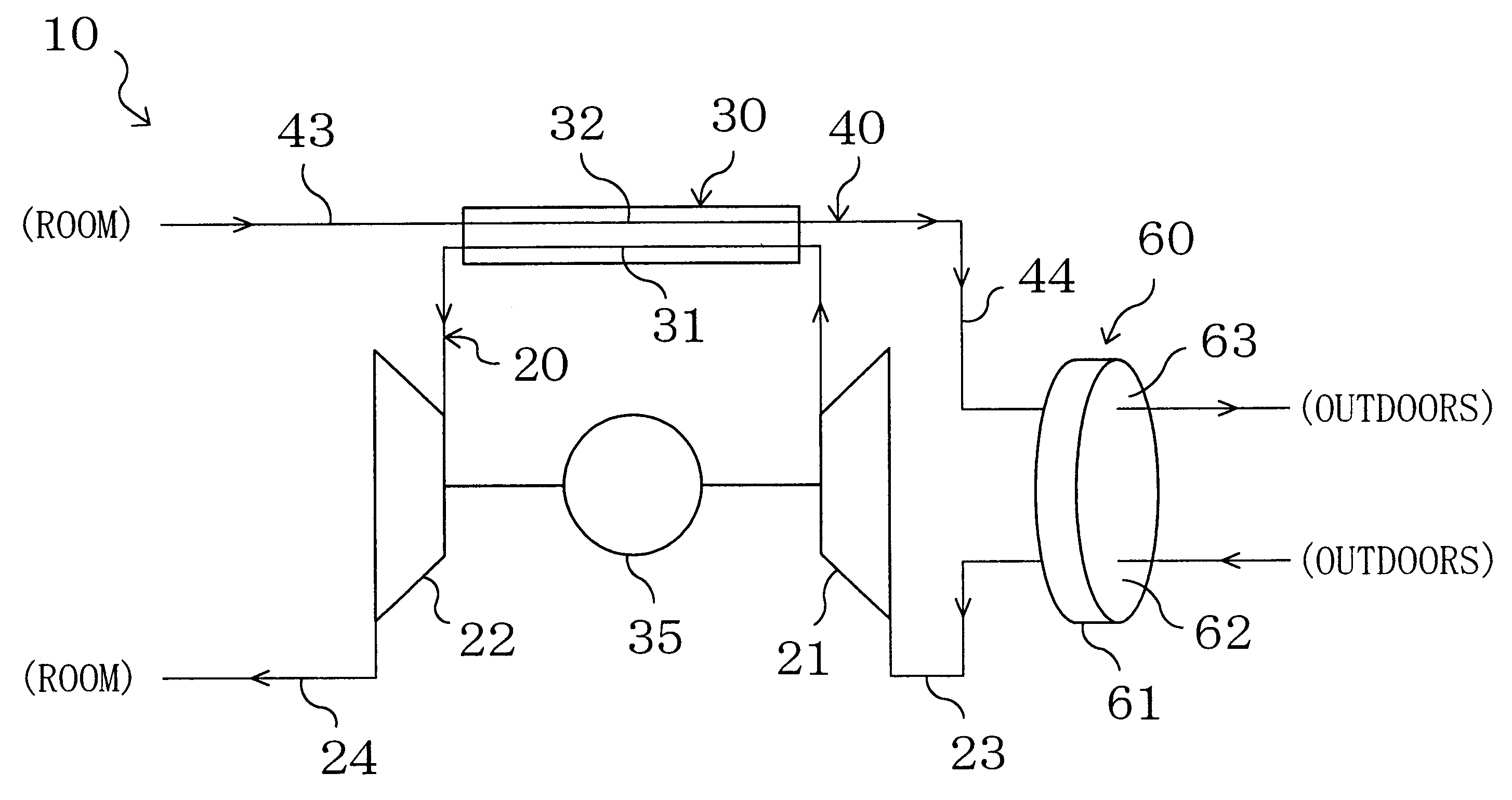
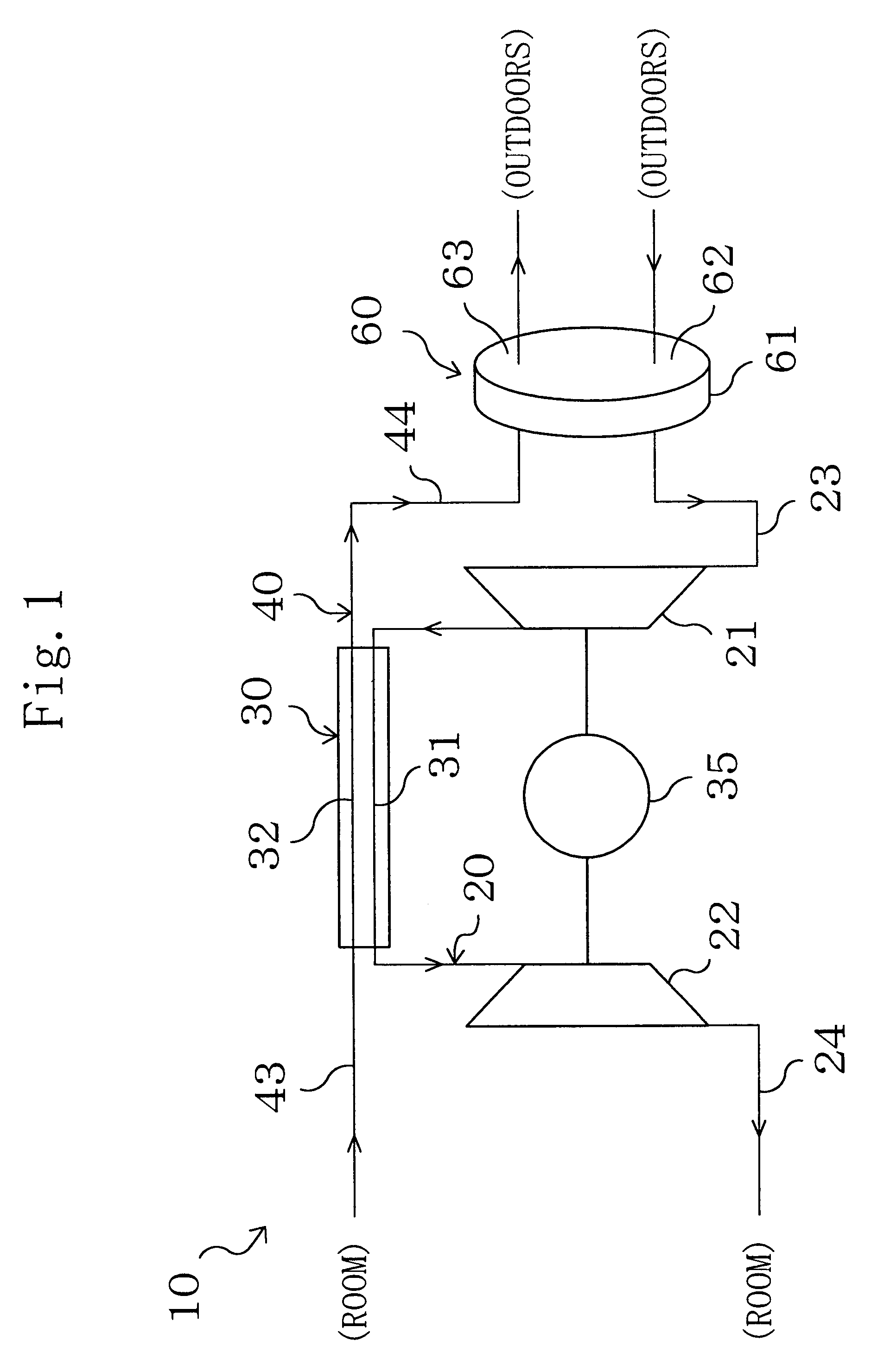
According to Embodiment 1, moisture is adsorbed on or desorbed from the solid adsorbent of the rotor member (61) based on the difference in relative humidity between the primary and secondary airs. This implements dehumidification of the primary air. Therefore, dehumidification of the primary air is not limited to after it has been compressed by the compressor (21), unlike the case of dehumidifying it using the conventional vapor isolating membrane, and is possible also before it is supplied to the compressor (21). As a result, layout constraints of the dehumidifying mechanism (60) can be reduced, which enhances the design flexibility.

Further, since there is no need for such dehumidification between the compressor (21) and the expander (22) as conventionally done, an easy and reliable seal is provided between the compressor (21) and the expander (22) while the construction is maintained simply. This prevents leakage of the compressed air and ensures that the e...

embodiment 2

Effects of Embodiment 2

According to Embodiment 2, the following effects can be obtained in addition to the effects of Embodiment 1.

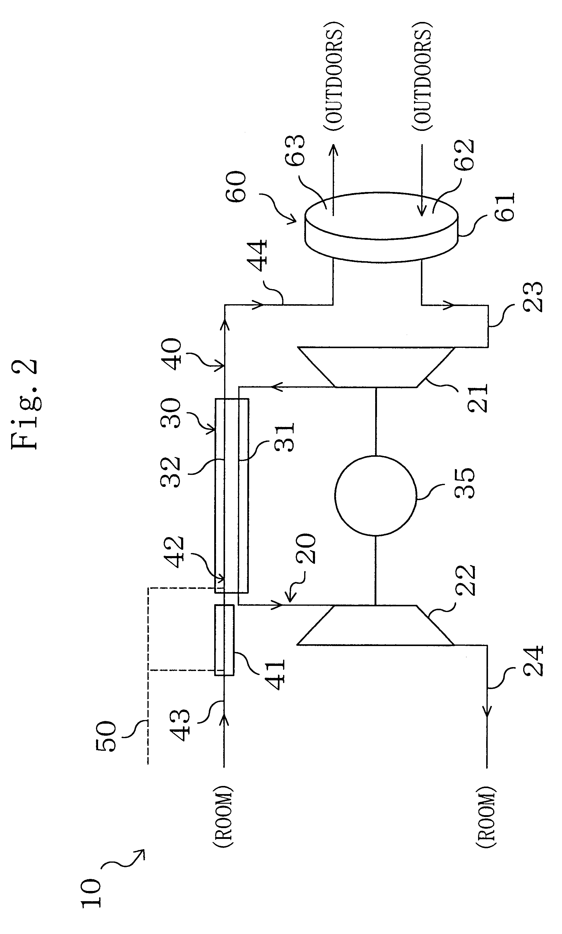
Specifically, in this embodiment, the humidifier / cooler (41) is provided to supply moisture to the secondary air, and the secondary air is cooled therein and then supplied to the heat exchanger (30). Further, the water introducing section (42) is provided to supply moisture to the secondary air in the heat absorption side passage (32), and latent heat of evaporation of the moisture is used to cool the primary air in the heat exchanger (30). Therefore, the primary air can be cooled to a still lower temperature in the heat exchanger (30) than in the case of Embodiment 1. This makes it possible to drop the air temperature at the inlet of the expander (22) to a lower degree. As a result, this embodiment enables further reduction in the input to the compressor (21) while maintaining the refrigerating capacity and thereby provides improved COP (coefficient of ...

embodiment 3

Effects of Embodiment 3

According to Embodiment 3, the following effects can be obtained in addition to the effects of Embodiment 2.

Specifically, according to this embodiment, the temperature of the primary air at the inlet of the compressor (21) can be elevated as compared with Embodiment 2. Further, the temperature of the secondary air at the outlet of the heat exchanger (30) can be accordingly elevated. Even with the same absolute humidity, rise in temperature of the air leads to drop in relative humidity thereof. Further, in this embodiment, since the amount of moisture supplied to the secondary air in the humidifier / cooler (41) and the water introducing section (42) can be reduced, the absolute humidity of the secondary air at the outlet of the heat exchanger (30) can be lowered. Accordingly, in this embodiment, the rotor member (61) will release moisture to the secondary air higher in temperature and lower in relative humidity than that in Embodiment 2. This makes it possible t...


PUM


Abstract

A first channel (20) is formed by sequentially connecting a compressor (21), a heat exchanger (30) and an expander (22). In the first channel (20), an outside air is taken through a first inlet duct (23) and supplied to a room through a first outlet duct (24). A second channel (40) is formed by connecting both ends of the heat exchanger (30) to ducts (43, 44). In the second channel (40), a room air is taken through the second inlet duct (43) and discharged to outdoors through the second outlet duct (44). A moisture absorbing section (62) of a dehumidifying mechanism (60) is provided in the first inlet duct (23), while a moisture releasing section (63) thereof is provided in the second inlet duct (43). A rotor member (61) including a solid adsorbent rotatively moves between the moisture absorbing section (62) and the moisture releasing section (63). Air dehumidified in the moisture absorbing section (62) is supplied to the compressor (21).

Description

This invention relates to an air conditioning system using an air cycle.There is conventionally known a cooling system operating through an air cycle, as disclosed in Japanese Unexamined Patent Publication No. 62-102061. A cooling system of this kind includes a compressor, a heat exchanger and an expander, and is configured to suck an air into the compressor for compression, cool the compressed air in the heat exchanger and then expand it in the expander thereby obtaining a low-temperature air.Meanwhile, in the cooing system disclosed in the above publication, a vapor isolating device using a vapor isolating membrane is provided between the heat exchanger and the expander to isolate moisture from the compressed air being supplied to the expander. Once expanded in the expander, the air is reduced in temperature so that dropwise condensation may occur in the air. Therefore, the air as a working fluid for the air cycle is needed to undergo dehumidification prior to entry into the expan...

Claims


Application Information

Patent Timeline
IPC IPC(8): B64D13/00F24F5/00F24F3/14F25B9/00
CPCB64D13/00F24F3/1423F24F5/0085B64D2013/0662F24F2203/1016F24F2203/1032F24F2203/1056F24F2203/1068F24F2203/1084Y02T50/56Y02T50/50F24F3/1417F24F2203/028
Inventor PIAO, CHUN-CHENGSAKAMOTO, RYUICHIWATANABE, YUJIYOSHIMI, MANABUYONEMOTO, KAZUO
Owner DAIKIN IND LTD
Why Eureka
Try Eureka