Light-emitting diode lamp

a technology of light-emitting diodes and led lamps, which is applied in the direction of semiconductor devices for light sources, lighting and heating apparatus, transportation and packaging, etc., can solve the problems of limited heat dissipation area of metal plates b>713/b>, and significant reduction of led lamp lifespan

Inactive Publication Date: 2008-07-03
HON HAI PRECISION IND CO LTD
View PDF13 Cites 299 Cited by
  • Summary
  • Abstract
  • Description
  • Claims
  • Application Information

AI Technical Summary

Problems solved by technology

If not rapidly and efficiently removed, the heat produced may significantly reduce the lifespan of the LED.
In this particular example, it is difficult to combine a heat dissipation device to the LED lamp 620 since an interference problem arises between the conductive pins 624, 625 and the heat dissipation device when combined.
However, a heat dissipation area of the metal plate 713 is limited.

Method used


Image

  • Light-emitting diode lamp
  • Light-emitting diode lamp
  • Light-emitting diode lamp

Examples


Embodiment Construction

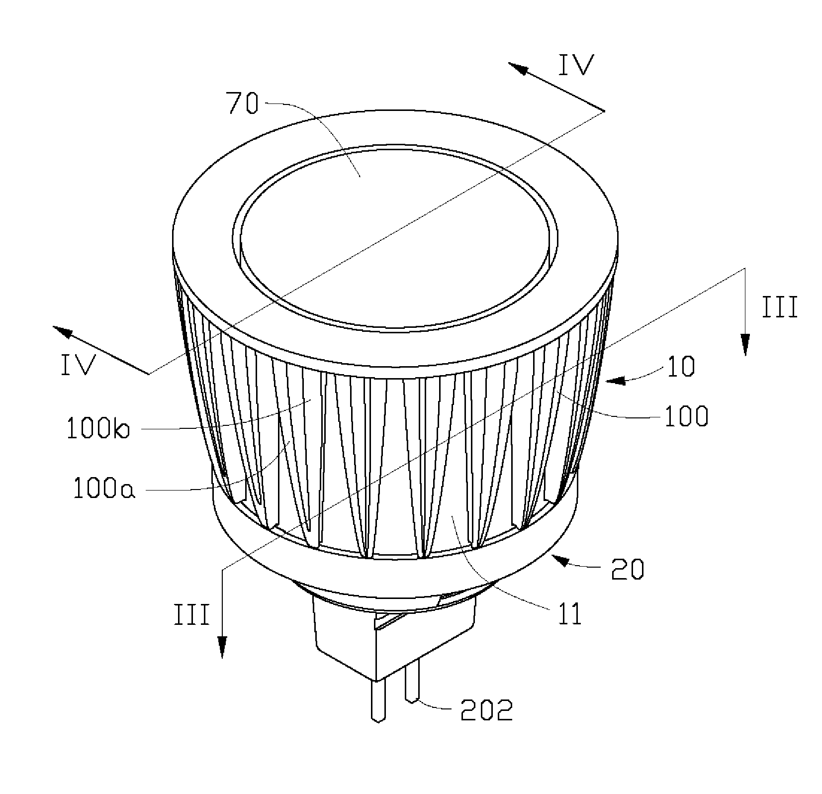
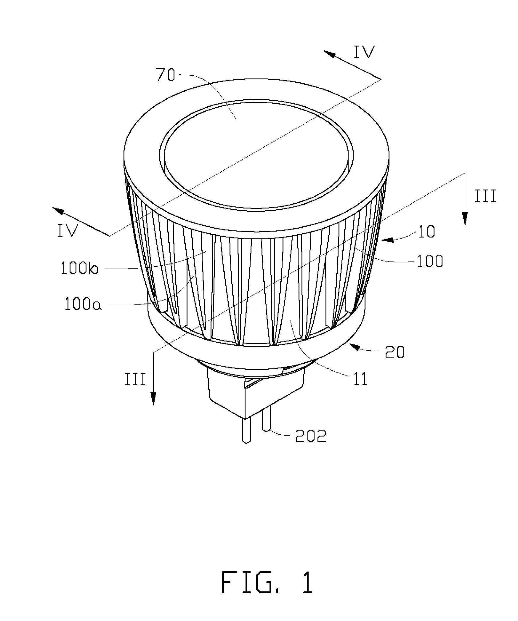
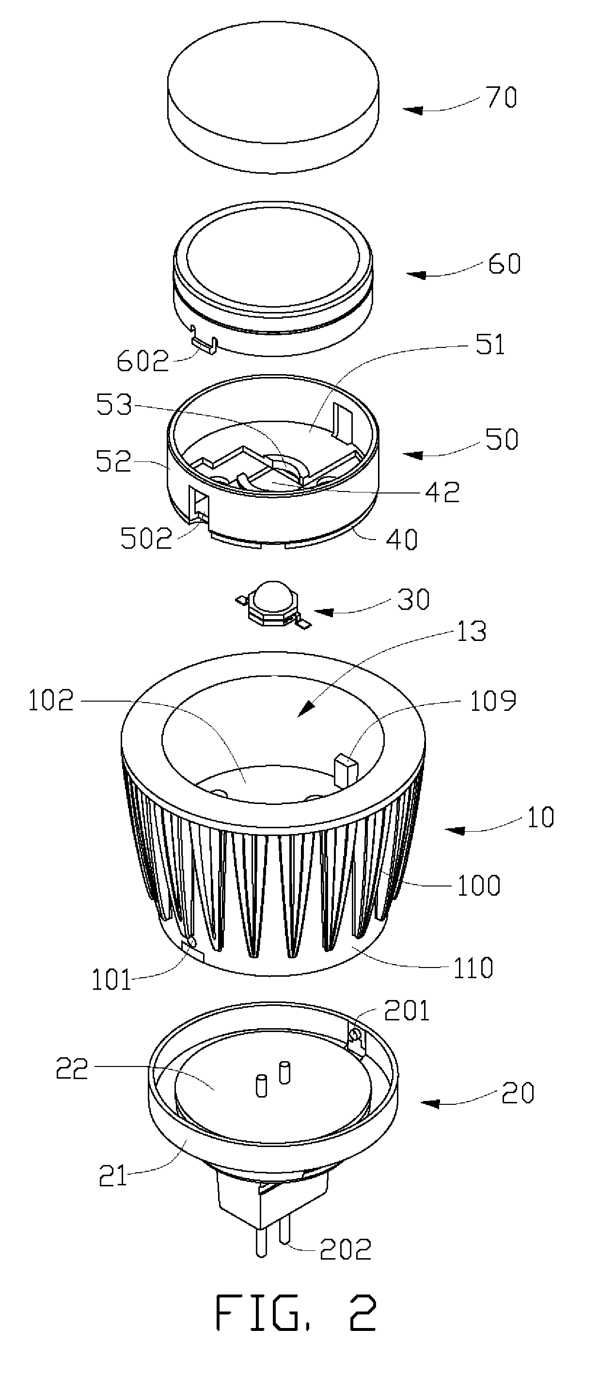
[0018]FIGS. 1-2 illustrate a light-emitting diode (LED) lamp in accordance with a preferred embodiment of the present invention. The LED lamp includes a heat sink 10, a lamp holder 20, an LED 30, a circuit board 40, a bracket 50, a reflector 60 and a lampshade 70.

[0019]Referring to FIG. 3-5, the heat sink 10 is made of aluminum alloy. Alternatively, the heat sink 10 can be made of other materials of high heat conductivity, such as copper and stainless steel. The heat sink 10 is truncated cone-shaped. An outer diameter of the heat sink 10 gradually increases along an axial direction from a bottom end to a top end thereof. The top end of the heat sink 10 is open, whilst the bottom end of the heat sink 10 is closed. A cross section of the heat sink 10 along the axial direction thereof is approximately U-shaped (as shown in FIG. 4). The heat sink 10 includes a circular-shaped substrate 102, and a cylindrical-shaped sidewall 11 extending upwardly from an outer periphery of the substrate ...


PUM


Abstract

A light-emitting diode (LED) includes a heat sink (10) having a cross section along an axial direction thereof being U-shaped. The heat sink includes a substrate (102) and a sidewall (11) extending from an outer periphery of the substrate. A circuit board (40) is received in the heat sink and arranged on the substrate. At least one LED (30) is arranged on and electrically connected to the circuit board and thermally connected with the substrate of the heat sink. A plurality of fins (100) extend outwardly from an outer surface (110) of the sidewall of the heat sink. Each fin has a plurality of branches (100a, 100b) being connected together at the outer surface of the sidewall and being spaced from each other at outer-peripheries thereof.

Description

BACKGROUND OF THE INVENTION[0001]1. Field of the Invention[0002]The present invention relates generally to light-emitting diode (LED) lamps, and more particularly to an LED lamp with improved heat dissipation ability so that heat generated by the LEDs can be effectively removed.[0003]2. Description of Related Art[0004]Light-emitting diodes (LEDs) are highly efficient light sources currently used widely in such fields as automobiles, screen displays, and traffic light indicators. When the LED gives off light, heat is also produced. If not rapidly and efficiently removed, the heat produced may significantly reduce the lifespan of the LED. Therefore, a heat dissipation device is required to dissipate the heat from the LED.[0005]FIG. 6 is a cross-sectional view of an LED lamp 620 in accordance with related art. The LED lamp 620 includes an LED die 621, an outer packaging layer 622, and a pair of conductive pins 624, 625. The LED die 621, which is placed in a recess defined in the conduc...

Claims


Application Information

Patent Timeline
Patent Type & Authority Applications(United States)
IPC IPC(8): F21V29/00B60Q1/06
CPCF21V29/004F21Y2101/02F21V19/0015F21V29/745F21V29/70F21V29/74F21K9/137F21K9/233F21Y2115/10
Inventor ZHU, MING-WUTAN, LI-KUANGLIN, YEU-LIHHU, TSENG-HSIANG
Owner HON HAI PRECISION IND CO LTD
Why Eureka
Try Eureka