Compact optical modulator

a technology of optical modulator and optical divider, which is applied in the field of optical communication to achieve the effect of high compactness

Active Publication Date: 2008-07-10
WSOU INVESTMENTS LLC +1
View PDF5 Cites 5 Cited by
  • Summary
  • Abstract
  • Description
  • Claims
  • Application Information

AI Technical Summary

Benefits of technology

[0007]I have developed—according to the present invention—a highly compact DQPSK modulator design. The design is so compact because it uses the electro-absorption (EA) effect rather than the electro-refraction effect, and because it requires only one interferometer.

Problems solved by technology

The design is so compact because it uses the electro-absorption (EA) effect rather than the electro-refraction effect, and because it requires only one interferometer.

Method used


Image

  • Compact optical modulator
  • Compact optical modulator
  • Compact optical modulator

Examples


Embodiment Construction

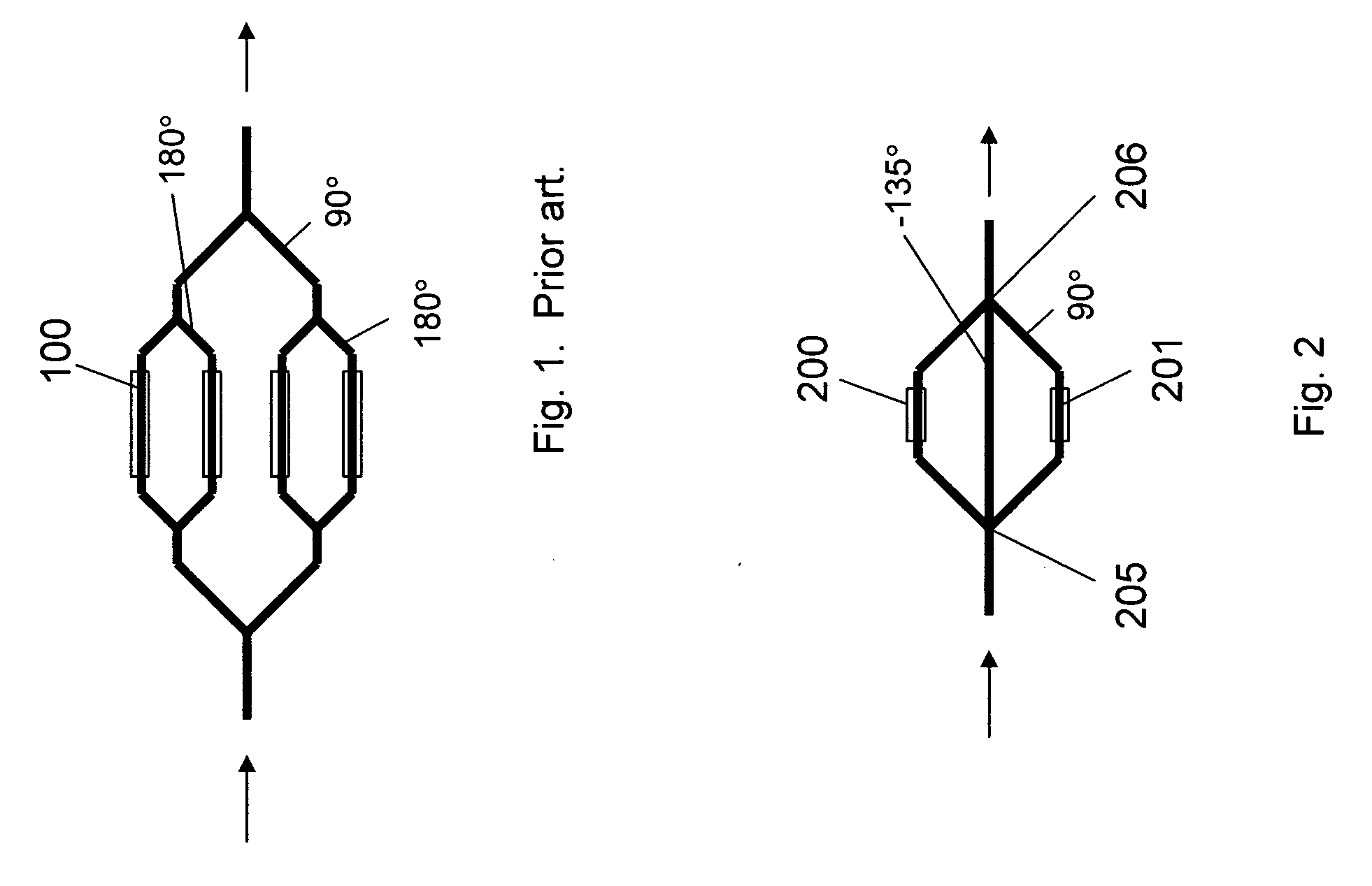
[0017]A prior art DQPSK modulator design is shown in FIG. 1. It consists of two small Mach-Zehnder interferometers (MZIs) contained within a large MZI. Each small MZI constains phase modulators, 100. This modulator is large in size because it has multiple stages and because phase modulators are long. Also, high-speed phase modulators are challenging to fabricate because of their traveling-wave nature.

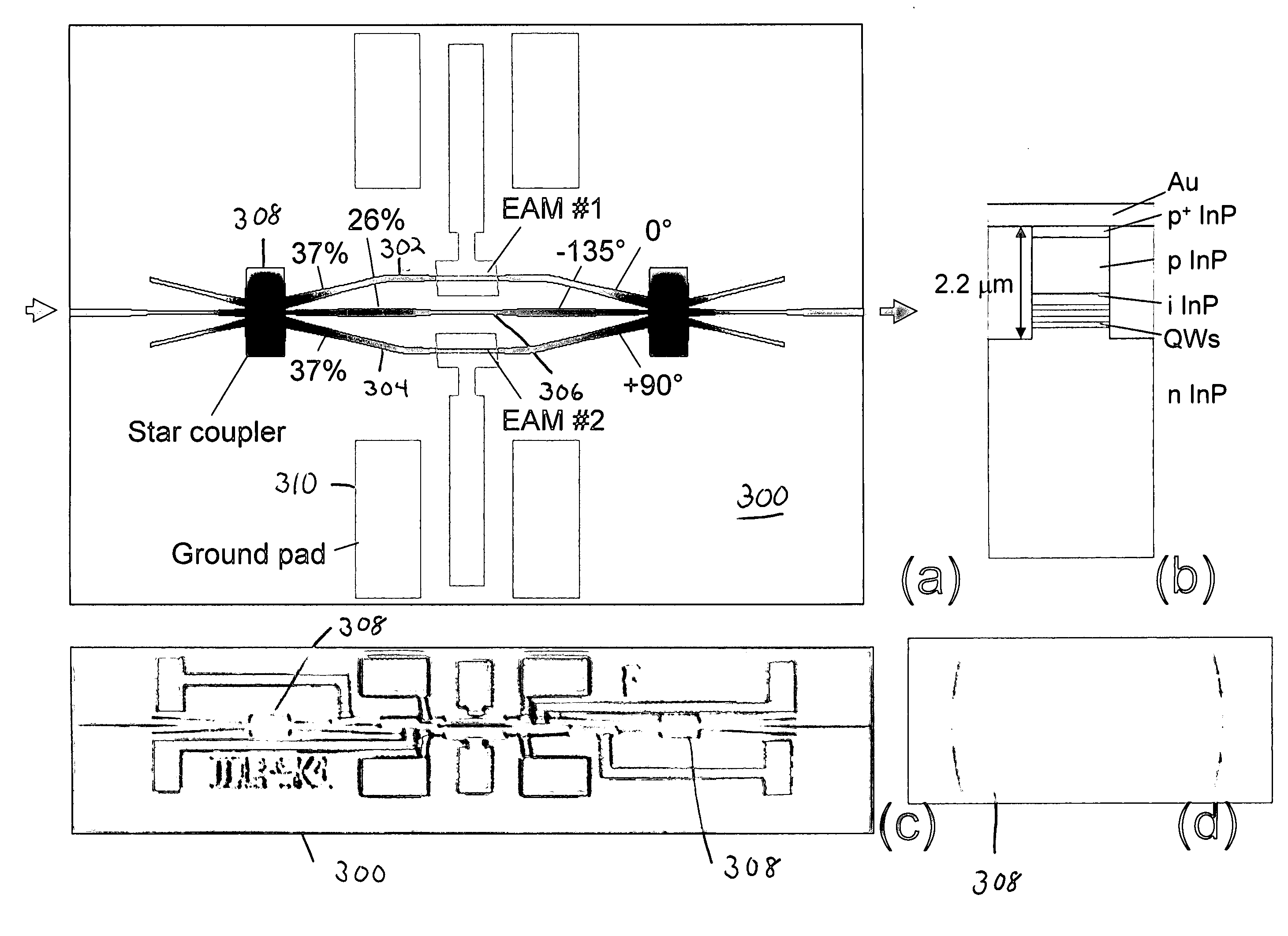
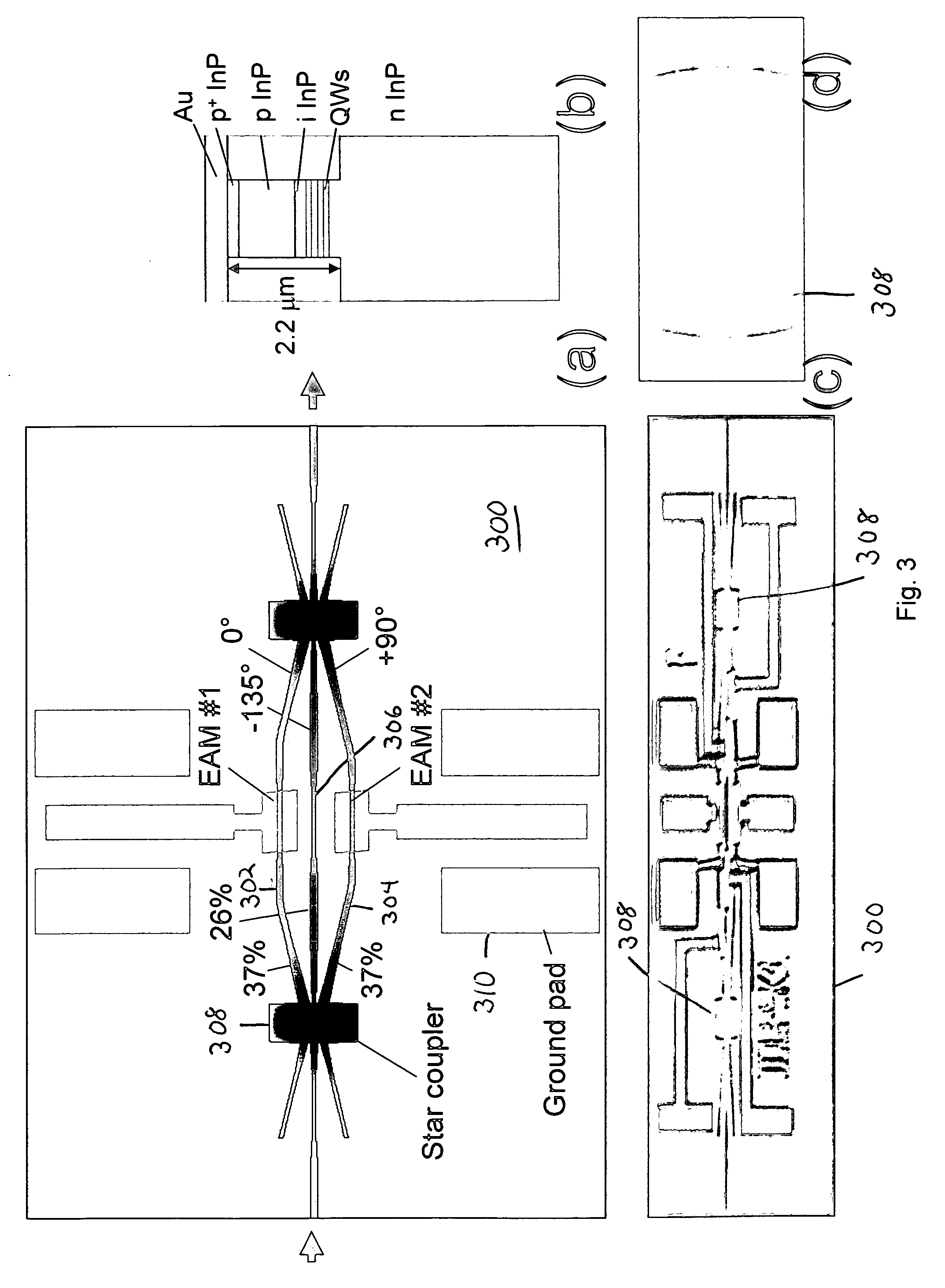
[0018]Our proposal to make a compact DQPSK modulator is to instead use the electro-absorption (EA) effect in InP. An InP EA modulator (EAM) can be as short as 100 μm. Thus, up to modulation bandwidths of 40-50 GHz, the EAM can be operated as a lumped element instead of a traveling-wave structure, R. G. Walker, “High-speed III-V semiconductor intensity modulators,”IEEE J. Quant. Electron, vol. 27, pp. 654-667, March 1991, and H. Kawanishi, Y. Yamauchi, N. Mineo, Y. Shibuya, H. Murai, K. Yamada, and H. Wada, “EAM-integrated DFB laser modules with than 40 GHz bandwidth,”IEEE Photon. Techno...


PUM

PropertyMeasurementUnit
sizeaaaaaaaaaa
lengthaaaaaaaaaa
widthaaaaaaaaaa

Abstract

We present a novel design for an optical differential quadrature phase shift keying modulator comprised of two intensity modulators in a three-arm interferometer.

Description

CROSS-REFERENCE TO RELATED APPLICATIONS[0001]This application claims priority of Provisional Application Ser. No. ______, filed on Jan. 9, 2007, which is incorporated herein by reference.FIELD OF THE INVENTION[0002]This invention relates generally to the field optical communications and in particular to an optical modulator for creating a high-speed optical data signal.BACKGROUND OF THE INVENTION[0003]Next generation Ethernet is likely to have a data rate around 100 Gb / s. One possibility to accomplish 100-Gb / s transmission is the use of a multiplex of parallel lower-speed channels. However, the parallel approach typically has a low spectral efficiency, requires temporal de-skewing among channels, and has a large footprint or consumes significant chip real-estate. Another possibility is the use of a single 100-Gb / s serial channel. With a multi-level modulation format, such as differential quadrature phase-shift keying (DQPSK), in which the data is encoded using four different phase l...

Claims


Application Information

Patent Timeline
Patent Type & Authority Applications(United States)
IPC IPC(8): G02F1/035
CPCH04B10/5561H04B10/505
Inventor DOERR, CHRISTOPHER RICHARD
Owner WSOU INVESTMENTS LLC
Why Eureka
Try Eureka