
Arrow rest

a technology of arrow rest and arrow head, which is applied in the direction of compressed gas guns, white arms/cold weapons, weapons, etc., can solve the problems of time-consuming and complicated mechanical adjustments of arrow res

Active Publication Date: 2008-07-24
GOOD SPORTSMAN MARKETING LLC
View PDF95 Cites 11 Cited by
  • Summary
  • Abstract
  • Description
  • Claims
  • Application Information

AI Technical Summary

Benefits of technology

[0009]It is one object of this invention to provide an arrow rest that does not interfere with the fletching or vanes of an arrow, as the arrow discharges over the arrow rest.
[0010]It is another object of this invention to provide an arrow rest that has relatively minimal frictional contact with an arrow shaft which the arrow rest supports.
[0011]It is yet another object of this invention to provide an arrow rest that can quickly and easily accommodate different diameters of differently sized arrow shafts.
[0017]According to a preferred embodiment of this invention, the arrow rest may further include a pair of generally rigid members, each extending from the frame in a similar manner as the spring arms. Preferably, each rigid member includes a distal end that terminates at a distance away from the distal end of the respective spring arm. In the configuration of the arrow rest as described, the rigid members maintain the arrow shaft within a vicinity of the vertical post and prevent the arrow shaft from falling out of a generally ready position, particularly preventing the arrow shaft from clattering against the frame and / or falling completely out of the arrow rest.

Problems solved by technology

But because arrow shafts are now manufactured with outside diameter lengths in a wide range, it is often necessary to make complicated and time-consuming mechanical adjustments to the arrow rest when changing to an arrow shaft with a different diameter.

Method used


Image

  • Arrow rest
  • Arrow rest
  • Arrow rest

Examples


Embodiment Construction

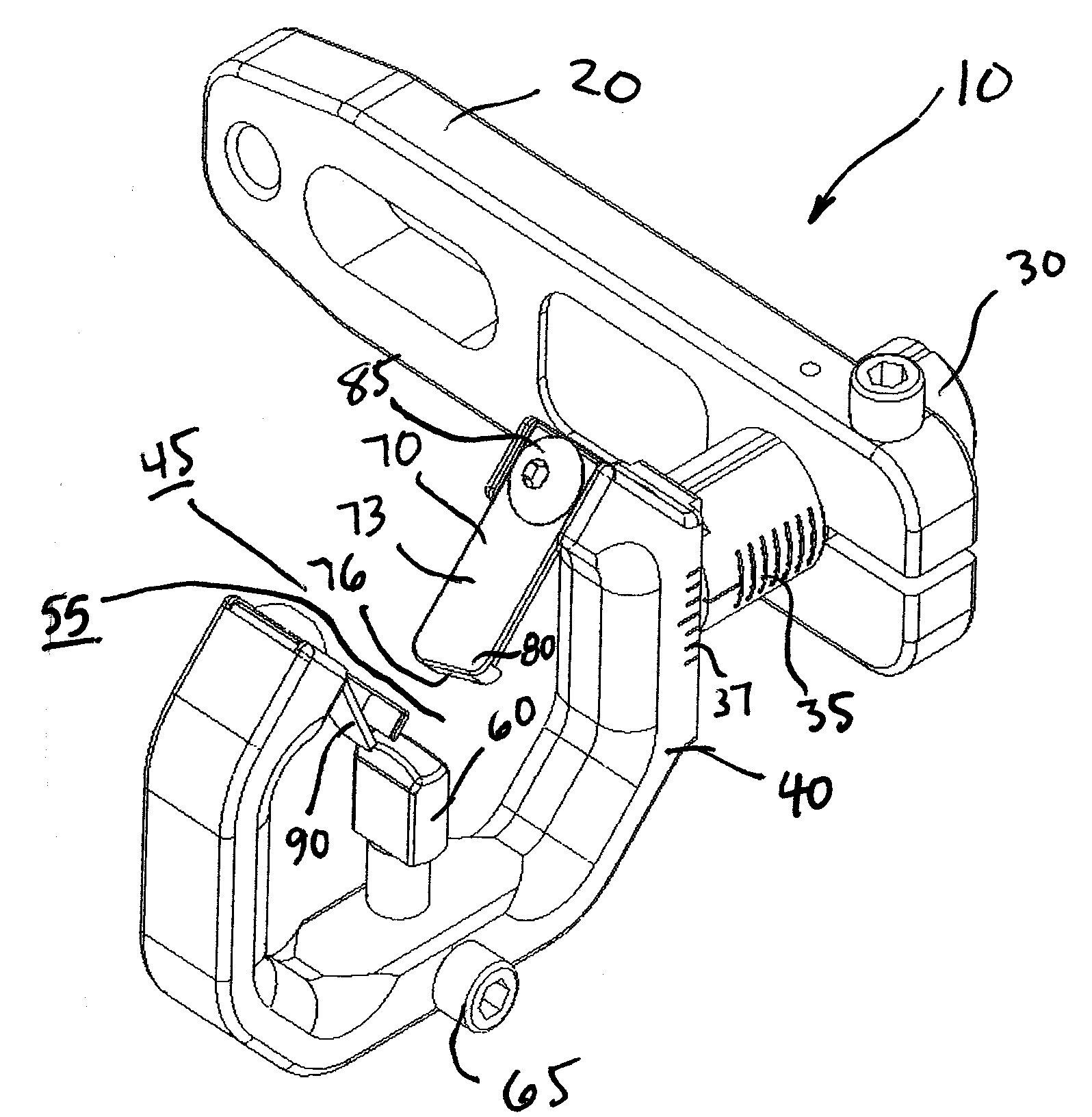
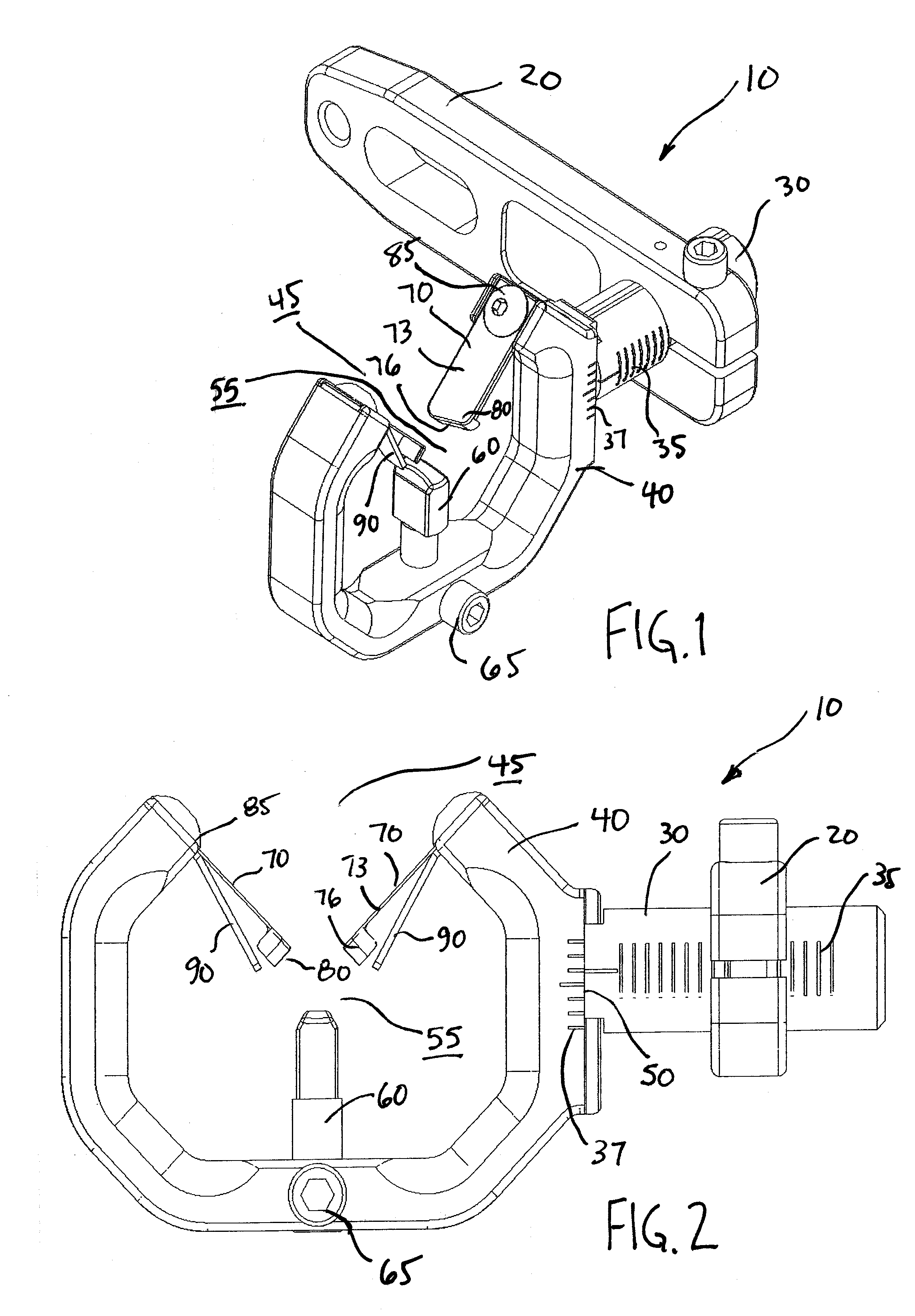
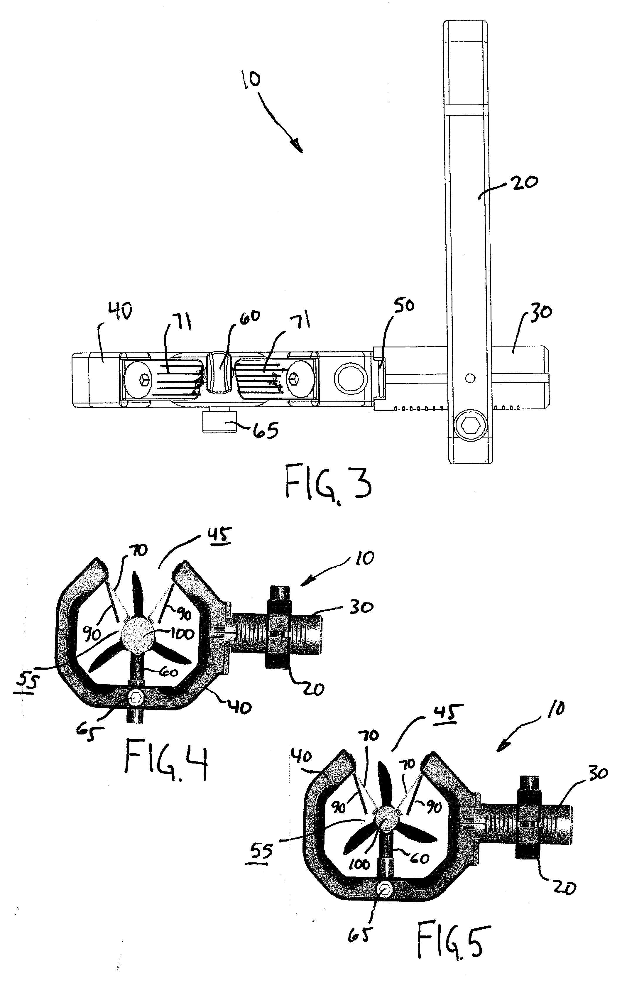
[0034]FIGS. 1-8 and 14 show arrow rest 10 according to various preferred embodiments of this invention. Arrow rest 10 is preferably used to maintain arrow shaft 100, such as shown in FIGS. 4-8, in a fixed position prior to and during launch of the arrow.

[0035]Referring to FIG. 1, arrow rest 10 is shown in a perspective view. Arrow rest 10 is preferably attached with respect to an archery bow in a manner known to those having ordinary skill in the art. According to one preferred embodiment of this invention, bracket 20 is connected with respect to the archery bow to maintain arrow rest 10 in a generally fixed position relative to the archery bow. Bracket 20 is preferably generally rigid and configured to support arrow rest 10 and arrow shaft 100.

[0036]Arrow rest 10 preferably further includes frame 40 connected with respect to bracket 20. According to a preferred embodiment of this invention, frame 40 includes two opposing ends 42 defining opening 45. Opening 45 preferably permits pa...


PUM


Abstract

An arrow rest for an archery bow includes a frame and a vertical post extending upwardly from the frame so that the frame at least partially encircles the vertical post to form an arrow shaft pass-through. The arrow rest further includes a pair of spring arms, brushes and / or rollers extending generally toward the arrow shaft pass-through.

Description

CROSS REFERENCE TO RELATED APPLICATION[0001]This application claims the benefit of U.S. Provisional Patent Application Ser. No. 60 / 881,736, filed 18 Jan. 2007.BACKGROUND OF THE INVENTION[0002]1. Field of the Invention[0003]This invention relates to an arrow rest that captures an arrow shaft within a frame prior to launch.[0004]2. Description of Prior Art[0005]Some conventional arrow rests, often referred to as shoot-thru arrow rests, allow an arrow to discharge without the fletching or the vanes touching the arrow rest. For example, U.S. Pat. Nos. 5,137,006 and 5,285,764 each disclose two opposing support arms through which one vane may pass during discharge of the arrow.[0006]Other conventional arrow rests support an arrow shaft at two positions lower than the centerline of the arrow shaft. For example, U.S. Pat. Nos. 3,865,096, 3,935,854, 4,686,956, 4,748,964 and 4,827,895 teach supporting members that form point contact or line contact with an arrow shaft at two positions lower t...

Claims


Application Information

Patent Timeline
IPC IPC(8): F41B5/14
CPCF41B5/143
Inventor HARWATH, FRANK A.MIZEK, ROBERT S.
Owner GOOD SPORTSMAN MARKETING LLC
Learn More