Bevel quadrant and gearbox louver blower system

a gearbox and louver technology, applied in the field of circular saws, can solve the problems of preventing the user from following the desired cut line to produce a straight and accurate, little consideration has been given to directing the air in any particular direction or for any apparent purpose other than to expel the air from inside the motor housing

Inactive Publication Date: 2005-08-18
CREDO TECH CORP +1
View PDF19 Cites 11 Cited by
  • Summary
  • Abstract
  • Description
  • Claims
  • Application Information

AI Technical Summary

Benefits of technology

[0007] The preferred embodiment of the present invention comprises one or more louvers in the housing of a hand tool such as a circular saw, which direct the air toward a specific location that includes the work piece, together with providing openings in other components of the tool located between the louvers and the portion of the work piece that the saw is approaching so that sawdust and other debris that is produced during operation of the tool will be blown out of the way and will not interfere with the line of sight of the user.

Problems solved by technology

Even with the many improvements that have been made in the design of circular saws, a common problem that continues to exist is the accumulation of sawdust and / or other debris on the line of cut which hinders the user from following the desired cut line to produce a straight and accurate cut.
Because cutting of some materials, particularly those which are relatively thick, put a significant load on the motor, it is necessary to have an adequate flow of air near the motor to dissipate heat during operation.
While the circular saw designs are sufficient to expel the air and dissipate heat during operation, little regard has heretofore been made in directing the air in any particular direction or for any apparent purpose other than to expel the air from inside the motor housing.

Method used


Image

  • Bevel quadrant and gearbox louver blower system
  • Bevel quadrant and gearbox louver blower system
  • Bevel quadrant and gearbox louver blower system

Examples


Embodiment Construction

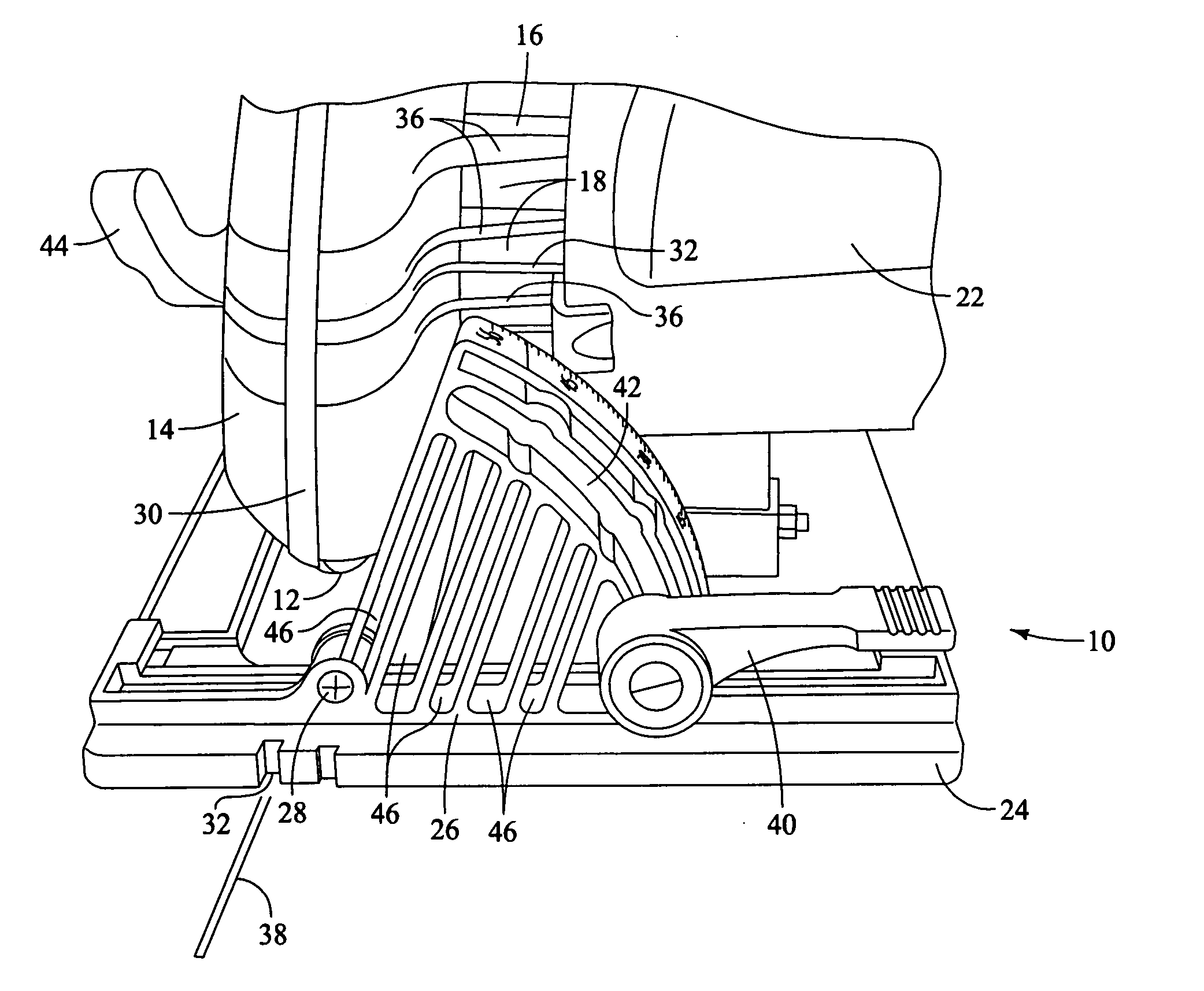
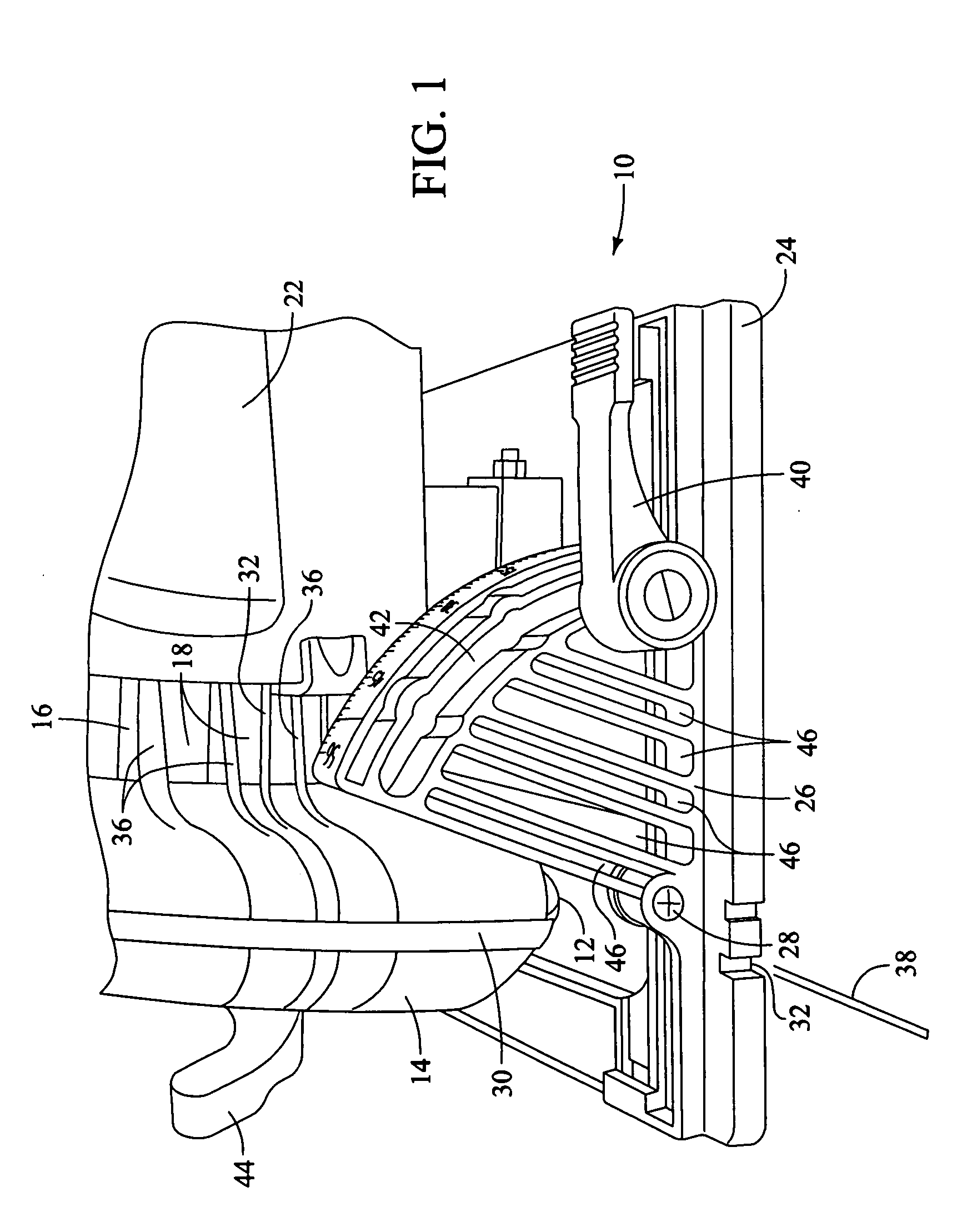
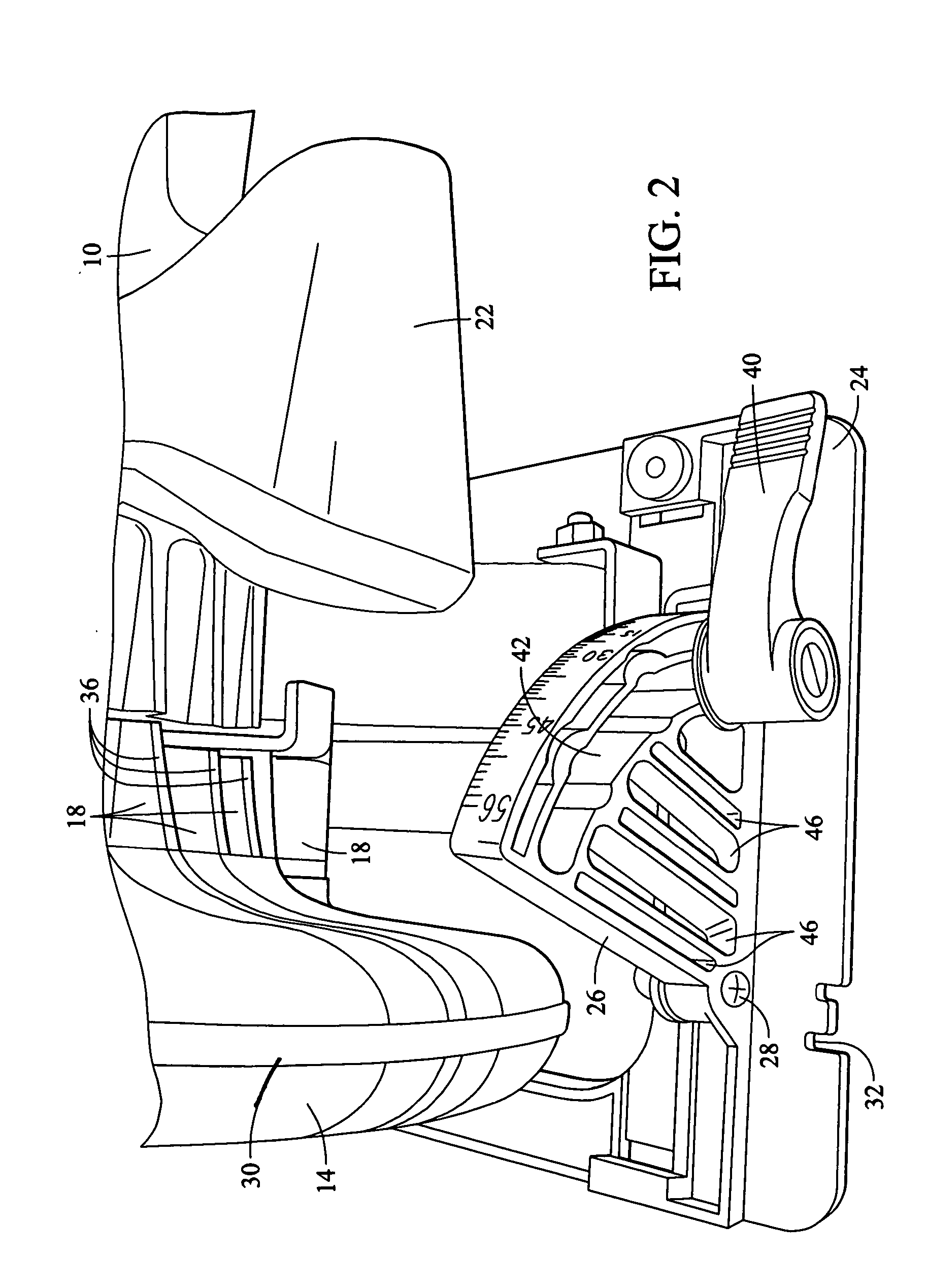
[0013] The preferred embodiment of the present invention is shown in FIGS. 1-4 and is directed to a circular saw of the type which has a motor housing 10 in which a motor 11 is located, a saw blade 12 that is protected by a blade housing 14, the blade housing 14 being attached to a gearbox end casting 16 that is in turn connected to the housing 10 and which has a number of vent openings 18 through which air from a fan 20 is expelled during operation of the circular saw. The circular saw also has a forward auxiliary handle 22 as well as a main handle (not shown) that is typical with such circular saws.

[0014] The circular saw also has a generally flat foot assembly 24 which preferably has an integrally formed quadrant structure 26 that is part of a bevel adjusting mechanism that is configured to enable the saw to cut a work piece at an adjustable bevel angle. Preferably, the bevel angle can be adjusted from perpendicular to approximately 55° from perpendicular by pivoting the motor h...


PUM

PropertyMeasurementUnit
bevel angleaaaaaaaaaa
angleaaaaaaaaaa
diameteraaaaaaaaaa

Abstract

A circular saw has one or more louvers in the housing which direct air exiting the housing toward a work piece, together with openings in other components of the saw located between the louvers and the work piece so that sawdust and other debris that is produced during operation of the saw will be blown out of the way and will not interfere with the line of sight of the user.

Description

BACKGROUND OF THE INVENTION [0001] The present invention generally relates to power hand tools and more particularly to circular saws. [0002] Power hand tools such as circular saws have been commonly known for decades and generally have a foot plate that slides on a work piece that is being cut, a circular saw blade that may have a diameter as small as a few inches or as large as seven or more inches, with the saw blade extending through an opening generally perpendicular to the plane of the foot. The saw is typically driven by an electric motor that is powered by either an AC or DC power source, the DC power source often being a battery pack or the like. [0003] Circular saws are commonly used on construction sites to saw boards that are used in framing a building or for cutting large plywood or other material sheets into smaller pieces, all of which are known to those skilled in the power hand tool art. Such circular saws have been the subject of much research and development and s...

Claims


Application Information

Patent Timeline
Patent Type & Authority Applications(United States)
IPC IPC(8): B23D59/00B23Q11/00B26D7/10B27B5/18B27B9/02
CPCB23D59/006B27B9/02B23Q11/005Y10T83/283Y10T83/293Y10T83/7697Y10T83/8773Y10T83/9435Y02P70/10
Inventor BOCKA, RALFWASCOW, JOSEPH Z.THOMAS, PATRICK B.
Owner CREDO TECH CORP
Why Eureka
Try Eureka