
Anchor system for personal belay safety lines

a technology of safety lines and anchor systems, which is applied in the direction of safety belts, rope railways, roads, etc., can solve the problems of increasing complexity and risk of the adventure cours

Inactive Publication Date: 2007-01-25
EXPONENT CHALLENGE TECH COOP VENNOOTSCHAP MET BEPERKTE AANSPRAKELIJKHEID
View PDF21 Cites 13 Cited by
  • Summary
  • Abstract
  • Description
  • Claims
  • Application Information

AI Technical Summary

Benefits of technology

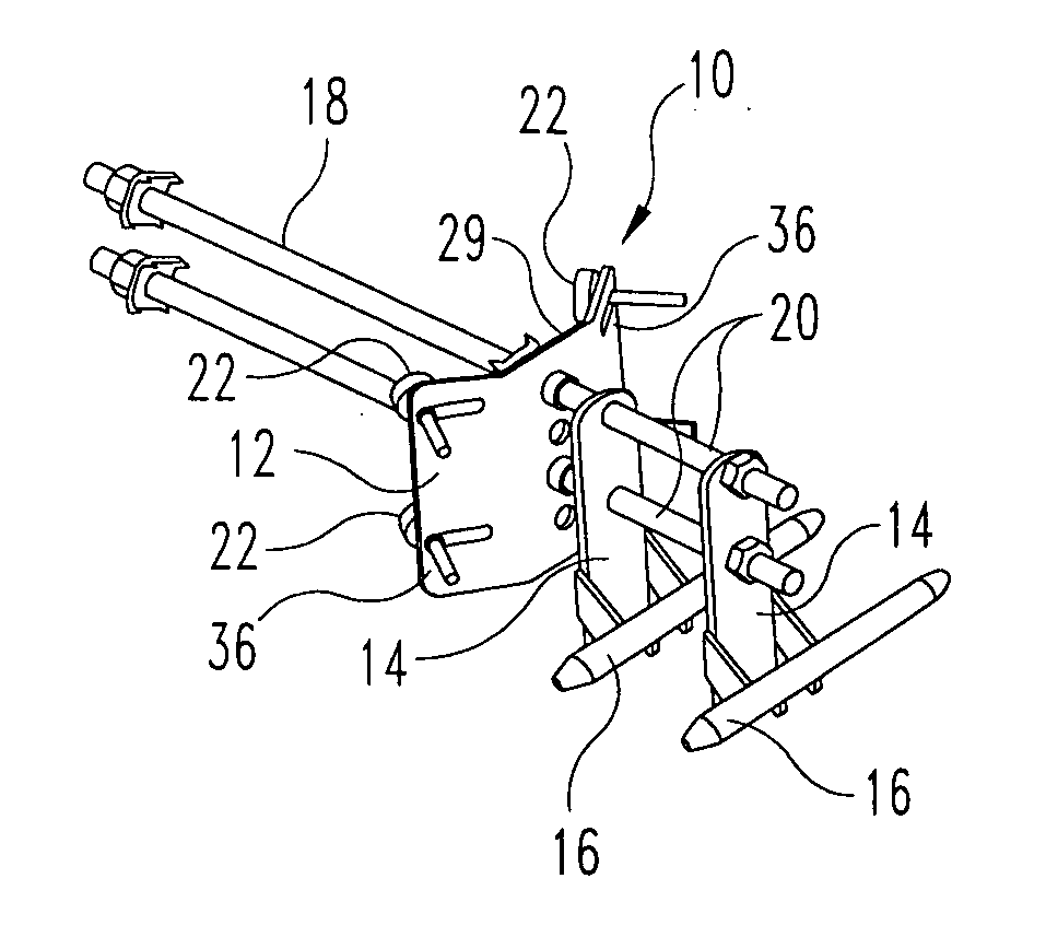
[0009] A ferrule or similar element is affixed to the end of the segment thereby trapping the profile tip on the end of the belay line segment. When the profile tip is threaded into the tubular body, the segment is fastened to the body, and ultimately to the support plate of the anchor system. This feature of the invention allows a complete belay line run to be formed by coupling segments of the run to the ends of a shuttle guide. This feature eliminates the problems associated with using a single continuous rope or cable to form the belay line run. This feature firmly anchors each end of the belay line segment to a particular anchor system. Moreover, a particular segment may be easily replaced by removing the profile tips at the ends of the segment from the corresponding shuttle guide. Not only does this feature simply replacement of a damaged rope or cable, it also allows for quick modification to the belay line course.
[0011] In a further feature of the invention, the mounting plate and support plates are provided with at least four openings or holes for receiving an anchor element, such as the threaded rod. For any given anchor system, only two anchor elements are usually necessary, which means that only two of the four holes are used to mount the plates to the anchor elements. This feature allows two like configured anchor systems to be mounted on a single vertical support. Thus, one pair of anchor elements extend through two of the four holes in one anchor system, while another pair of anchor elements extends through a different set of two holes. In this way, the anchor elements do not interfere with each other when passing through the vertical support.

Problems solved by technology

As participants demand more and more excitement, the adventure course will increase in complexity and risk.

Method used


Image

  • Anchor system for personal belay safety lines
  • Anchor system for personal belay safety lines
  • Anchor system for personal belay safety lines

Examples


Embodiment Construction

[0043] For the purposes of promoting an understanding of the principles of the invention, reference will now be made to the embodiments illustrated in the drawings and described in the following written specification. It is understood that no limitation to the scope of the invention is thereby intended. It is further understood that the present invention includes any alterations and modifications to the illustrated embodiments and includes further applications of the principles of the invention as would normally occur to one skilled in the art to which this invention pertains.

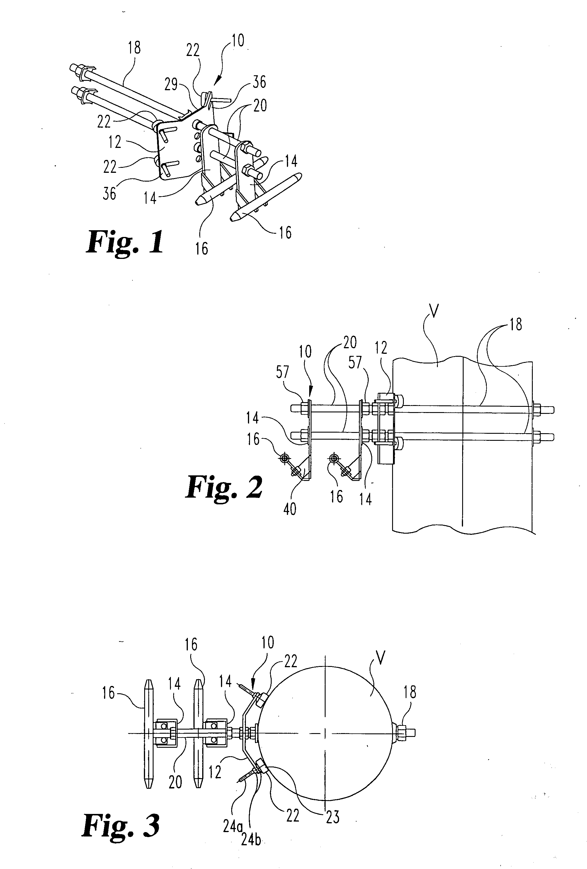
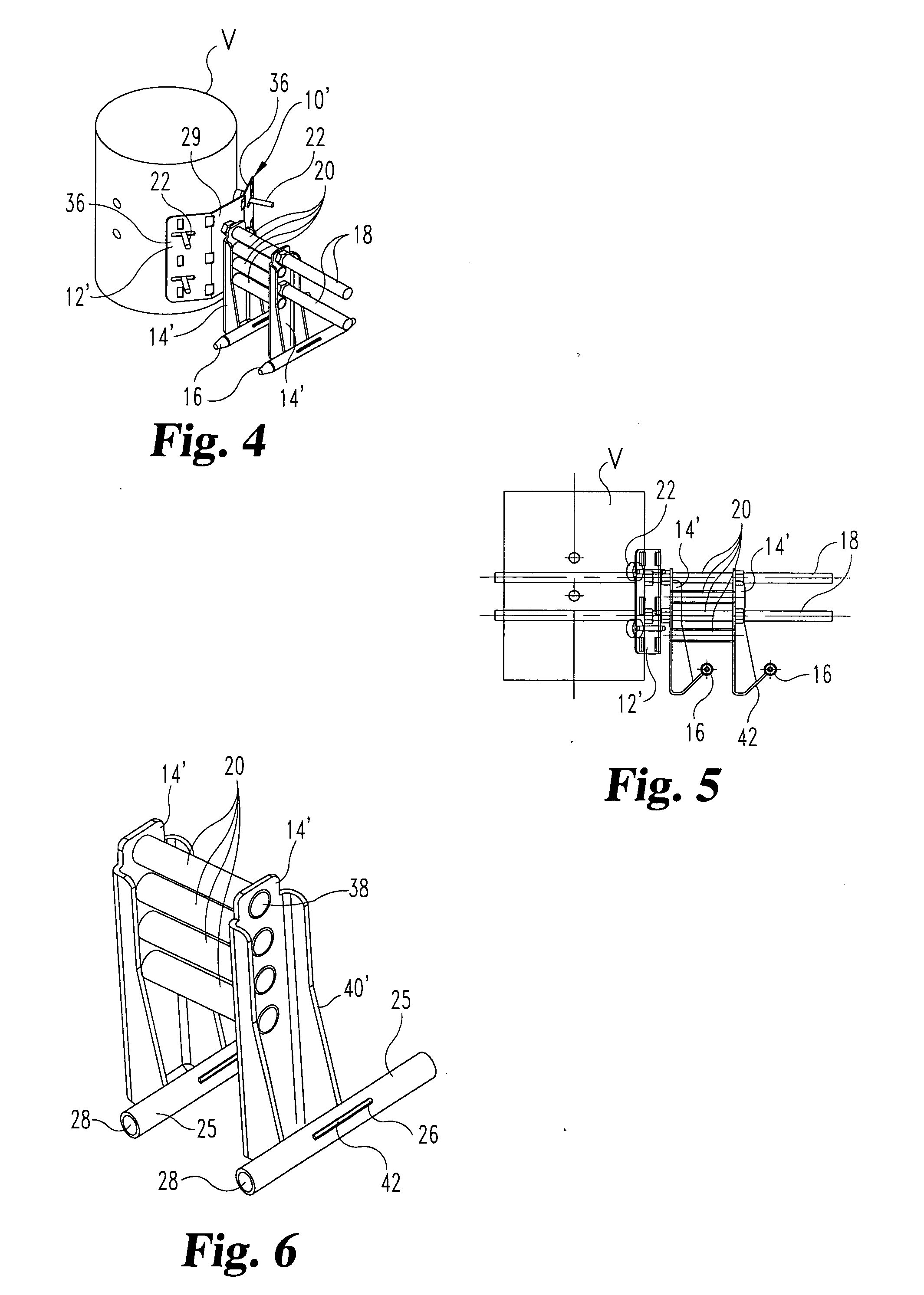
[0044] The present invention contemplates an anchor system for use with a continuous personal belay and fall arresting system. In one aspect of the invention, an anchor system 10, shown in FIGS. 1-3, is provided that is configured to be anchored to a vertical element, such as a tree, pole or wall. The anchor system includes a mounting plate 12 that is configured in the illustrated embodiment to engage a genera...


PUM


Abstract

An anchor system for a personal fall protection system having belay lines extending between vertical supports includes modular components adapted to be mounted to virtually any structure while permitting the installation of one or two belay line runs. A mounting plate interfaces with the vertical support, while one or two support plates are supported by the mounting plate and by anchor elements extending through each of the plates. Each support plate includes a shuttle guide and is configured to connect to belay line segments running between successive anchor systems and forming the complete belay line course. The fall protection system is further provided with a transfer station that allows a person to transfer from one belay line to another.

Description

BACKGROUND OF THE INVENTION [0001] The present invention relates to personal continuous belay systems for use with a suspended belay line system. In particular, the invention concerns a modular system for anchoring the suspended belay line system in a manner that easily accommodates the personal belay system. [0002] In a typical personal belay system, the user is fitted with a harness that may be removably clipped to a shuttle or glider. The shuttle is configured to slide easily along an array of belay lines in the form of suspended ropes or cables. Common forms of personal belay systems are used in the construction and building maintenance industries where workers are performing tasks at dangerous heights, such as high-rise building construction, window washing and roof repairs. In these common systems, the runs are relatively short and often include a cable run dedicated to each worker. Moreover, the cable runs are usually fixed, stable and predictable. For instance, in building c...

Claims


Application Information

Patent Timeline
Patent Type & Authority Applications(United States)
IPC IPC(8): A62B35/00E04G3/26A62B1/16
CPCA62B35/0068A62B35/0056
Inventor GEENS, STEFAANWIJCKMANS, FRANK
Owner EXPONENT CHALLENGE TECH COOP VENNOOTSCHAP MET BEPERKTE AANSPRAKELIJKHEID
Learn More