Heat dissipation device with heat pipes

a heat dissipation device and heat pipe technology, applied in the direction of envelopes/bags, paper/cardboard containers, semiconductor/solid-state device details, etc., can solve the problems of increasing heat generation, large amount of heat produced, and heat dissipation devices no longer able to efficiently remove heat from these cpus

Inactive Publication Date: 2008-07-24
HON HAI PRECISION IND CO LTD
View PDF15 Cites 20 Cited by
  • Summary
  • Abstract
  • Description
  • Claims
  • Application Information

AI Technical Summary

Problems solved by technology

During operation of an electronic device such as a computer central processing unit (CPU) mounted on a printed circuit board, a large amount of heat is often produced.
However, as electronics technology continues to advance, increasing amounts of heat are being generated by powerful state-of-the-art CPUs.
As a result, many conventional heat dissipation devices are no longer able to ef

Method used


Image

  • Heat dissipation device with heat pipes
  • Heat dissipation device with heat pipes
  • Heat dissipation device with heat pipes

Examples


Embodiment Construction

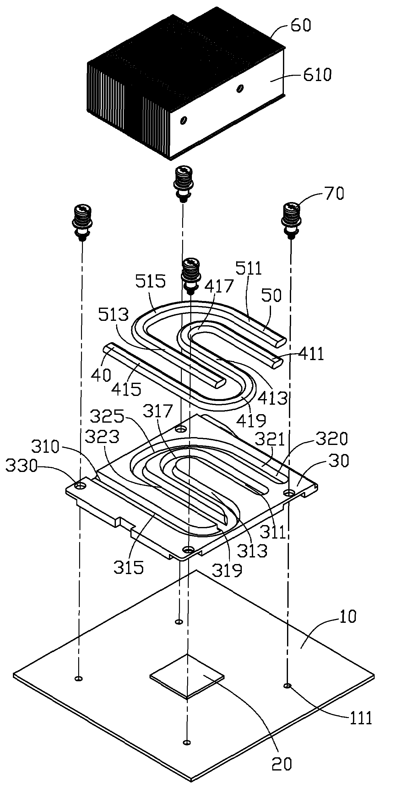
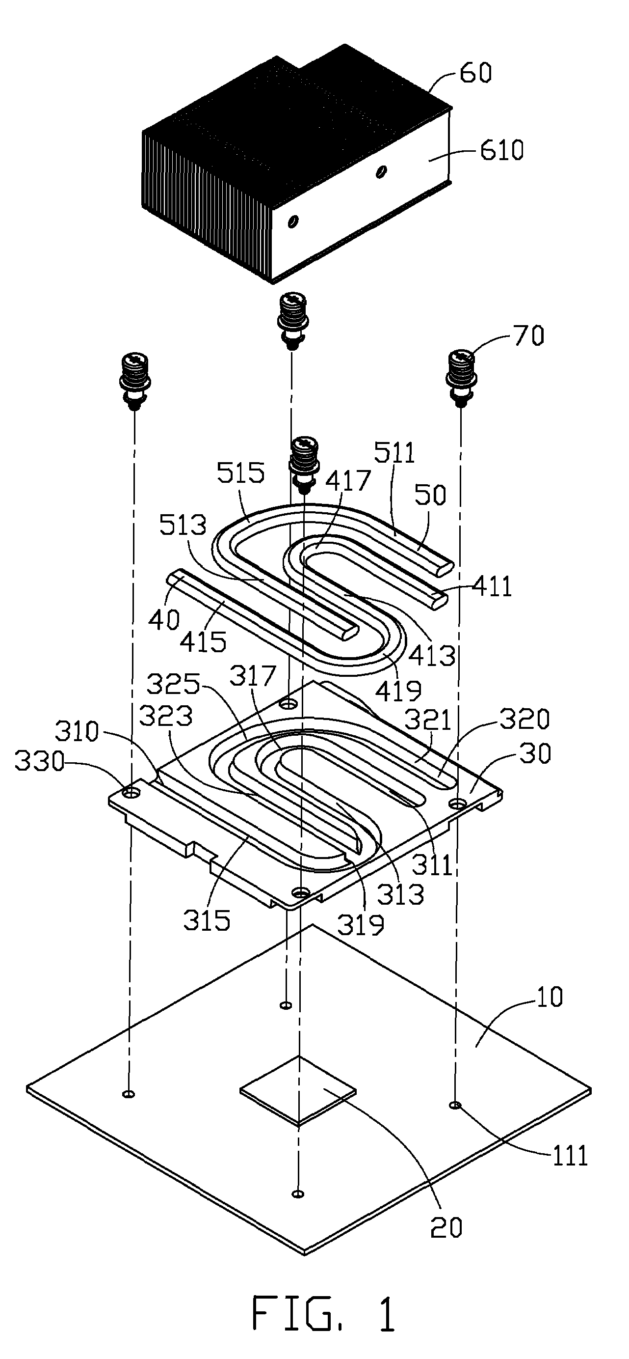
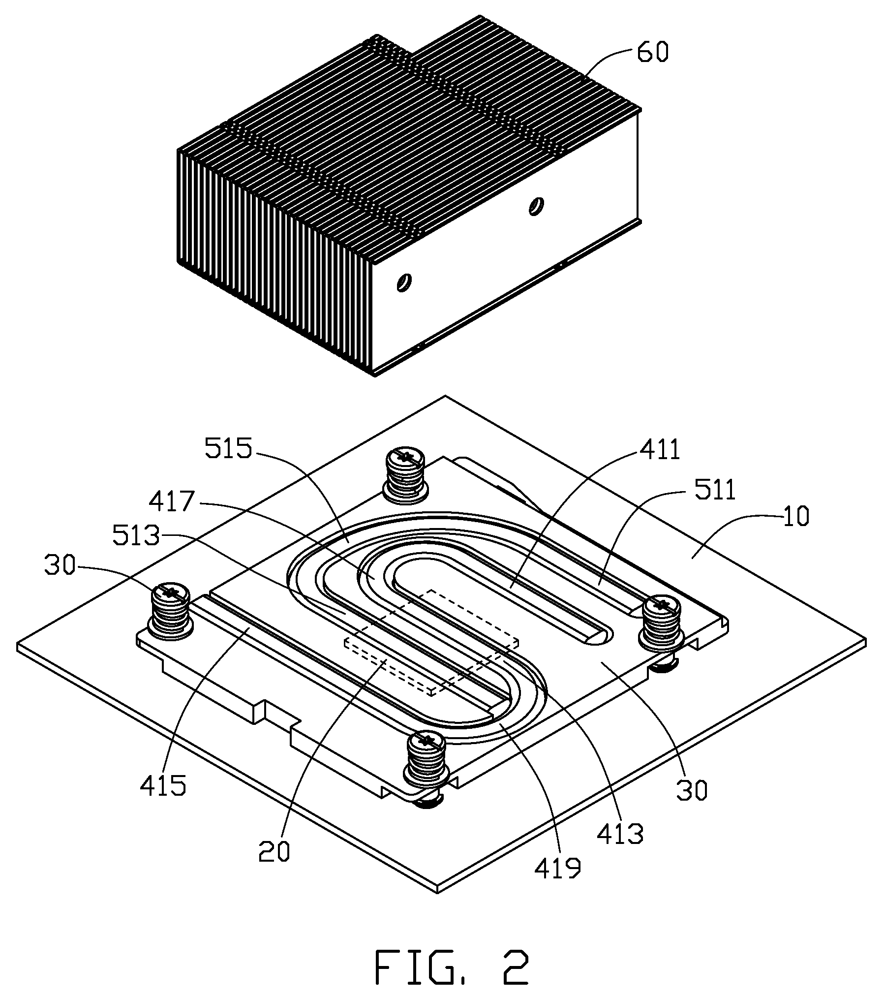
[0014]Referring to FIG. 1, a heat dissipation device in accordance with a preferred embodiment of the present invention is used for dissipating heat generated by a CPU 20 mounted on a printed circuit board 10. The heat dissipation device comprises a base 30, first and second heat pipes 40, 50 thermally arranged on the base 30, and a fin set 60 thermally contacting the base 30 and the heat pipes 40, 50.

[0015]The base 30 is a substantially rectangular metal plate having good heat conductivity, and has a bottom face (not labeled) for contacting the CPU 20 and a top face (not labeled) opposing the bottom face having the fin set 60 arranged thereon. A first groove 310 and second groove 320 are defined on the top face of the base 30 for receiving the first, second heat pipes 40, 50 therein. The first groove 310 is substantially S-shaped in profile, and comprises three parallel portions: a first linear portion 311, a second linear portion 313 and a third linear portion 315; the first groov...


PUM


Abstract

A heat dissipation device includes a base and a fin set thermally contacting the base. The base has a receiving portion for contacting to and absorbing heat from an electronic device and an extension portion surrounding the receiving portion. A first heat pipe is thermally engaged with the base. The first heat pipe is sinuous and includes a plurality of sections thermally engaged with the extension portion and the receiving portion of the base. A second heat pipe is thermally engaged with the extension portion and the receiving portion of the base. A middle linear section of the first heat pipe and an adjacent linear section of the second heat pipe are mounted to the base and located corresponding to the receiving portion of the base.

Description

BACKGROUND OF THE INVENTION [0001]1. Field of the Invention[0002]The present invention relates to heat dissipation devices for use in removing heat from electronic devices, and more particularly to a heat dissipation device incorporating heat pipes for improving heat dissipation efficiency of the heat dissipation device.[0003]2. Description of Related Art[0004]During operation of an electronic device such as a computer central processing unit (CPU) mounted on a printed circuit board, a large amount of heat is often produced. The heat must be quickly removed from the CPU to prevent it from becoming unstable or being damaged. Typically, a heat dissipation device is attached to an outer surface of the CPU to absorb heat from the CPU. The heat absorbed by the heat dissipation device is then dissipated to ambient air.[0005]Conventionally, a heat dissipation device comprises a solid metal base attached to the CPU, and a plurality of fins arranged on the base. The base is intimately attach...

Claims


Application Information

Patent Timeline
IPC IPC(8): F28D15/00B32B1/08
CPCF28D15/0233H01L23/427H01L2023/4081Y10T428/13H01L2924/0002H01L2924/00
Inventor JIN, ZHAOFU, MENGCHEN, CHUN-CHI
Owner HON HAI PRECISION IND CO LTD
Why Eureka
Try Eureka