Liquid crystal device and projector including the same

a liquid crystal cell and projector technology, applied in non-linear optics, instruments, optics, etc., can solve the problems of inability to obtain sufficient viewing angles and limited compensatory light entering in oblique directions, so as to improve light modulation of liquid crystal cells, reduce image contrast, and improve light control accuracy

Inactive Publication Date: 2008-07-24
SEIKO EPSON CORP
View PDF6 Cites 0 Cited by
  • Summary
  • Abstract
  • Description
  • Claims
  • Application Information

AI Technical Summary

Benefits of technology

[0019]According to this projector having the above liquid crystal device, such a phenomenon of conspicuous black and thus lowered image contrast in the display condition of the liquid crystal cell during the ON period can be prevented, for example. Accordingly, accuracy of light control, i.e., light modulation of the liquid crystal cell improves, and thus the projector provided according to this aspect of the invention can project a high-quality image by a simple structure.

Problems solved by technology

However, in principle, compensation for light entering in an oblique direction is limited, and sufficient characteristics of viewing angle cannot be obtained.

Method used


Image

  • Liquid crystal device and projector including the same
  • Liquid crystal device and projector including the same
  • Liquid crystal device and projector including the same

Examples


first embodiment

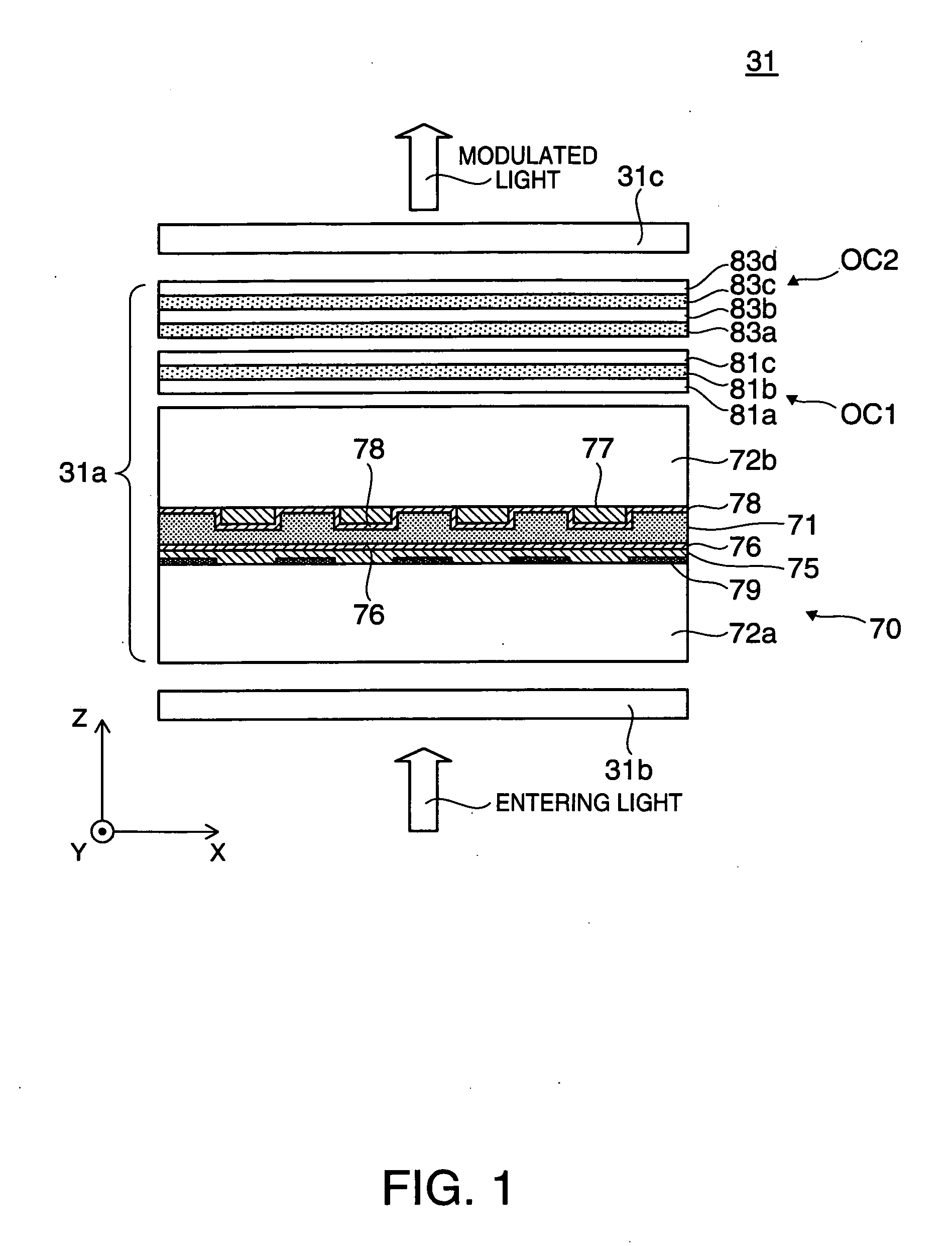
[0032]FIG. 1 is a cross-sectional view showing an enlarged structure of a liquid crystal light valve (light modulating device) as a liquid crystal device according to a first embodiment of the invention.

[0033]In a liquid crystal light valve 31 shown in the figure, a first polarizing filter 31b as a light entrance side polarizing element and a second polarizing filter 31c as a light exit side polarizing element constitute crossed nicols, for example. A polarization modulating unit 31a disposed between these first and second polarizing filters 31b and 31c is a liquid crystal panel which varies the polarization direction of entering light for each pixel in accordance with an input signal.

[0034]The polarization modulating unit 31a has a liquid crystal cell 70 which has a transparent first substrate 72a on the entrance side and a transparent second substrate 72b on the exit side with a liquid crystal layer 71 interposed therebetween. The liquid crystal layer 71 is constituted by liquid c...

second embodiment

[0051]A liquid crystal light valve as a liquid crystal device according to a second embodiment of the invention is now described. The liquid crystal light valve in the second embodiment is a modification of the liquid crystal light valve in the first embodiment, and the components not specifically touched upon are similar to those in the first embodiment and not repeatedly explained.

[0052]FIG. 5 is a cross-sectional view of an enlarged structure of the liquid crystal light valve in the second embodiment. In a liquid crystal light valve 131 shown in the figure, a third compensating element 183a constituting the second optical compensating member OC2 of the polarization modulating unit 31a is not formed by negative uniaxial crystal such as sapphire but by extended film having refractive index anisotropy similar to negative uniaxial characteristics such as TAC (triacetyl cellulose). This extended film exhibits relatively easily adjustable retardation and therefore is appropriate for ma...

third embodiment

[0055]A liquid crystal light valve as a liquid crystal device according to a third embodiment of the invention is now described. The liquid crystal light valve in the third embodiment is a modification of the liquid crystal light valve in the second embodiment, and the components not specifically touched upon are similar to those in the second embodiment.

[0056]FIG. 6 is a cross-sectional view illustrating an enlarged structure of the liquid crystal light valve in the third embodiment. In a liquid crystal light valve 231 shown in the figure, a compensating element portion 281a formed by an extended film having refractive index anisotropy similar to negative uniaxial characteristics such as TAC is included in the first optical compensating member 0C1 of the polarization modulating unit 31a. Similarly, a compensating element portion 283a formed by an extended film having refractive index anisotropy similar to negative uniaxial characteristics such as TAC is included in the second optic...


PUM

PropertyMeasurementUnit
refractive index anisotropyaaaaaaaaaa
refractive indexaaaaaaaaaa
thicknessaaaaaaaaaa

Abstract

A liquid crystal device includes a liquid crystal cell containing liquid crystal operating in twisted nematic mode, a first compensating element disposed either on the light entrance side or on the light exit side of the liquid crystal cell and made of an optical material having positive uniaxial characteristics, a second compensating element disposed either on the light entrance side or on the light exit side of the liquid crystal cell and made of an optical material having positive uniaxial characteristics, a third compensating element disposed at least either on the light entrance side or on the light exit side of the liquid crystal cell and made of an optical material which satisfies the following condition for parameters Re and Rth concerning refractive index anisotropy: −Rth<Re<Rth, and a pair of polarizing elements between which the liquid crystal cell, the first compensating element, the second compensating element, and the third compensating element are disposed.

Description

BACKGROUND[0001]1. Technical Field[0002]The present invention relates to a liquid crystal device for image formation, and further to a projector including this liquid crystal device.[0003]2. Related Art[0004]A liquid crystal projector in related art has a twisted nematic type liquid crystal panel and two compensating optical elements disposed between the liquid crystal panel and a light entrance polarizing plate or a light exit polarizing plate. Each of the two compensating optical elements is constituted by a uniaxial element having an optic axis disposed in the rubbing direction and inclined at a predetermined angle to the entrance surface (see JP-A-2004-198650). According to this type of liquid crystal projector, pre-tilt of liquid crystal can be compensated by the adjustment of the optic axes or thicknesses of the compensating optical elements positioned in the vicinity of the liquid crystal panel for improvement over contrast.[0005]When low-cost and easily processible crystal i...

Claims


Application Information

Patent Timeline
Patent Type & Authority Applications(United States)
IPC IPC(8): G02F1/13363G02F1/1333
CPCG02F1/13363G02F1/133634G02F1/1396G02F2413/14G02F2413/10G02F2413/13G02F2413/04
Inventor ENDO, TAKASHIYANAI, HIROAKI
Owner SEIKO EPSON CORP
Why Eureka
Try Eureka