Optical element and projection type image display apparatus having optical element therein

a technology of optical elements and projection-type images, which is applied in the direction of optical elements, natural mineral layered products, instruments, etc., can solve the problems of increasing the cost of apphire, and achieve the effect of reducing the cost and increasing the contrast of images

Inactive Publication Date: 2006-11-23
HITACHI LTD
View PDF40 Cites 0 Cited by
  • Summary
  • Abstract
  • Description
  • Claims
  • Application Information

AI Technical Summary

Benefits of technology

[0006] In the conventional technology mentioned above, since sapphire has crystallographic axis, birefringence of light tends to occur and the image contrast tends to be lowered. Accordingly, when the element is assembled, it is necessary to adjustably align the position and angle of the element to the direction of the crystallographic axis of sapphire. Further, sapphire increases the cost.

Problems solved by technology

Further, sapphire increases the cost.

Method used


Image

  • Optical element and projection type image display apparatus having optical element therein
  • Optical element and projection type image display apparatus having optical element therein
  • Optical element and projection type image display apparatus having optical element therein

Examples


first embodiment

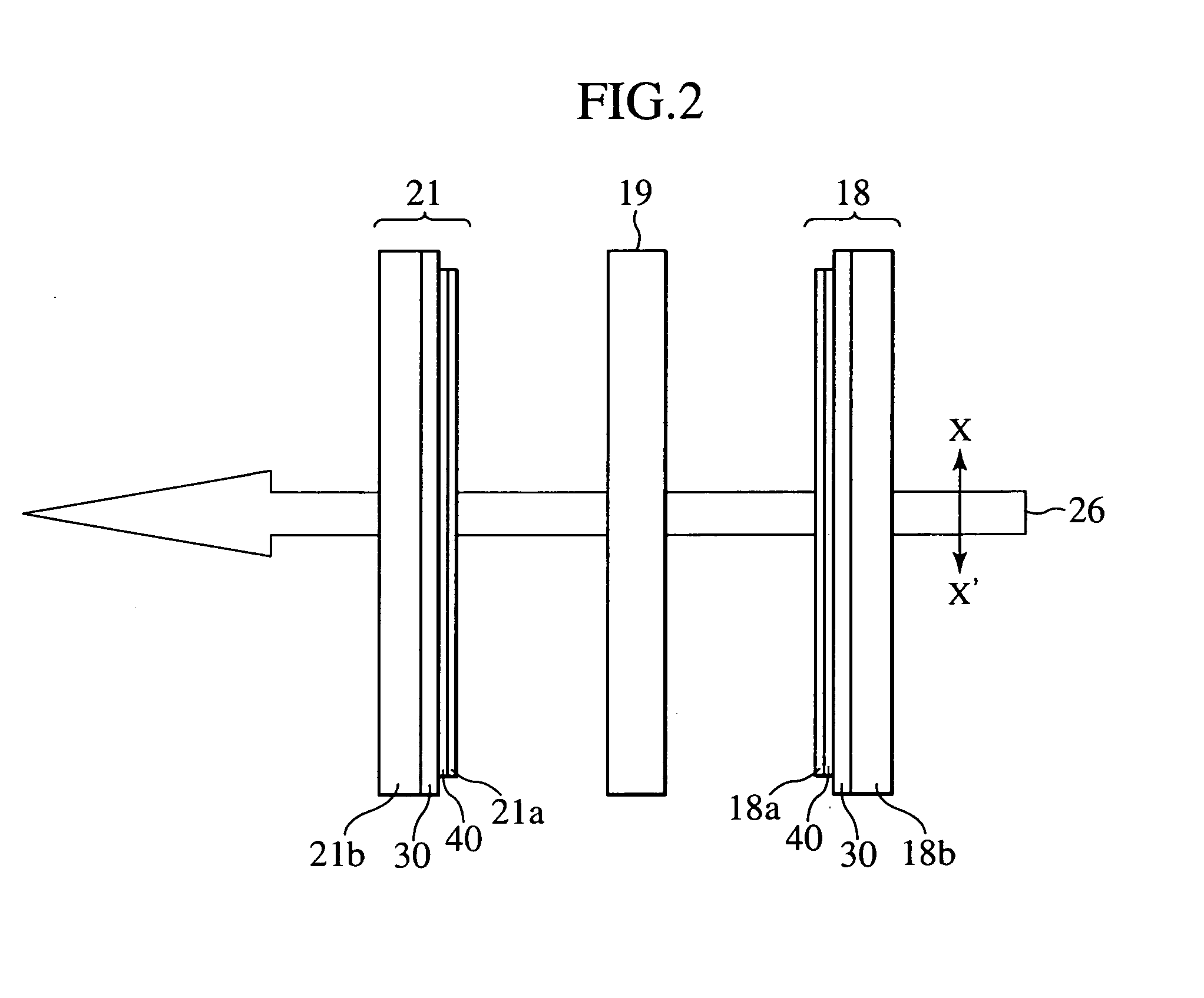
[0049]FIG. 6 is a diagram illustrating the constitution of a projection type image display apparatus using the constitution of the arrangement of FIG. 5 by way of example. In FIG. 6, are shown view angle compensation plates 50R, 50G, 50B for R light, G light, and B light respectively. Other reference numerals are identical with those in the case of the first embodiment shown in FIG. 3. Each of the view angle compensation plates 50R, 50G, and 50B has a constitution within a range included in FIG. 4. Also in the constitution of FIG. 6, constitution elements including from the light source 1 to the projection lens unit 23 constitute an optical unit in the projection type image display apparatus.

[0050] In the constitution described above, the S polarization light of the R light directed to the incident side polarization plate 18R of the image display element 19R for the R light is aligned in polarization direction through the transmission of the component along the direction of the tran...

second embodiment

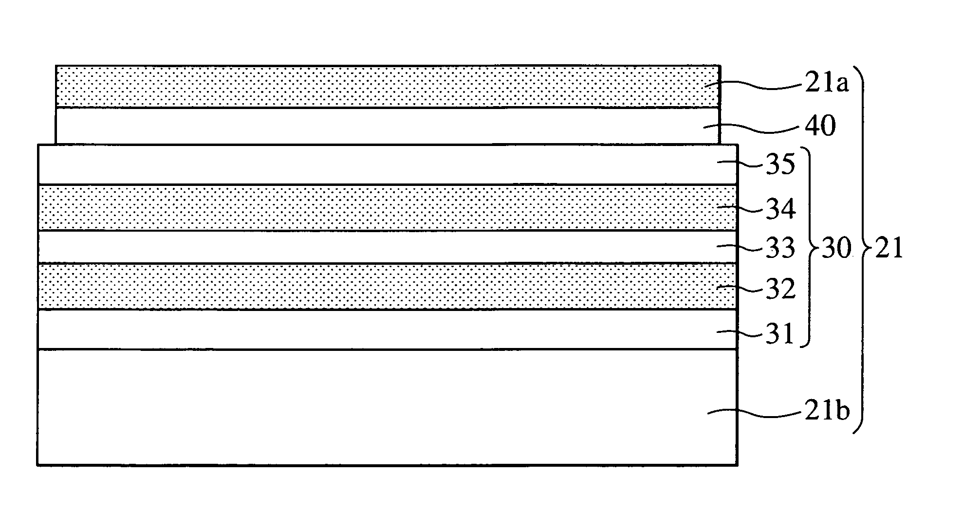
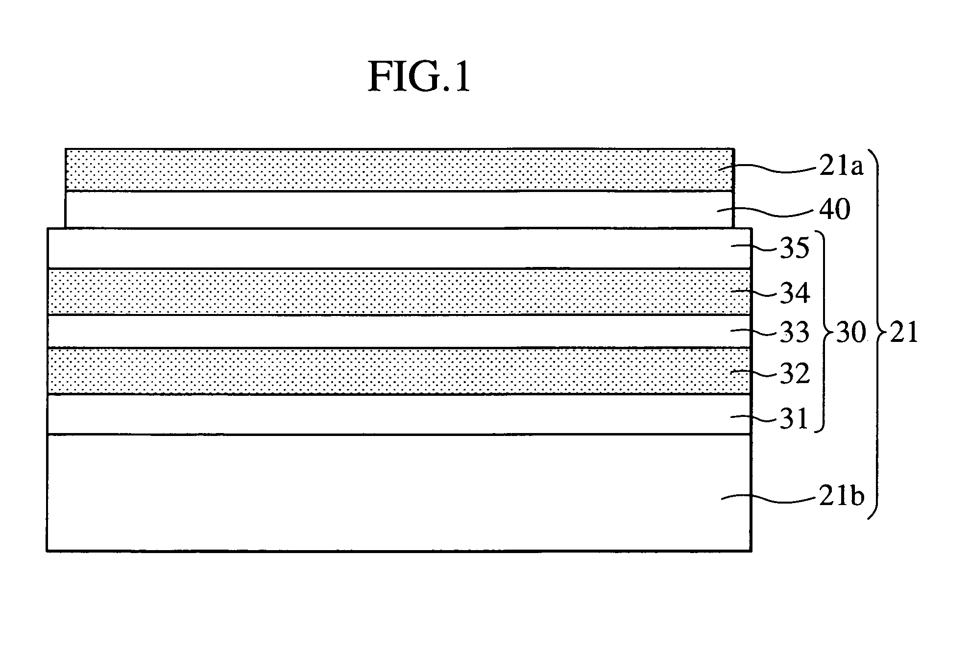
[0055] described with reference to FIGS. 4 to 6, since the magnesium oxide substrate has the cubic system structure, it causes neither birefringence nor change of the linear polarization to the elliptic polarization, and the absorption and loss of light is small, enabling bright and high contrast image display. Further, it is not necessary that the magnesium oxide substrate is adjustably aligned to the direction of the transmission axis (absorption axis) of the image display element layer or the view angle compensation element layer when the polarization plate or the view angle compensation plate is assembled. This improves the efficiency of the assembling operation. Further, since the magnesium oxide substrate itself can be manufactured easily, the manufacturing cost can be reduced. Further, since the magnesium oxide substrate has satisfactory heat conductivity, heat generated in the polarization plate or the optical member can be dissipated effectively, suppressing a temperature ...


PUM

PropertyMeasurementUnit
incident angleaaaaaaaaaa
permeableaaaaaaaaaa
phaseaaaaaaaaaa

Abstract

In a projection type image display apparatus, it is intended to reliably facilitate assembly of optical members for polarization treatment and phase difference compensation of light. The optical members are each configured such that a protective layer such as a magnesium fluoride layer or an aluminum oxide layer is formed by vapor deposition over a light permeable substrate of cubic system structure comprising, for example, magnesium oxide and an adhesive layer is provided on the protective layer for fixing the element layers of a polarization element, a view angle compensation element, etc.

Description

CLAIM OF PRIORITY [0001] The present application claims priority from Japanese application serial No. P2005-145150, filed on May 18, 2005, the content of which is hereby incorporated by reference into this application. BACKGROUND OF THE INVENTION [0002] 1. Technical Field of the Invention [0003] The present invention relates to a projection type image display apparatus such as a liquid crystal projector and a projection type rear projection television set. In addition, the invention relates to a constitution of an optical member disposed in an image display element on the light incident side or light emission side thereof so as to execute polarization treatment and optical phase difference compensation. [0004] 2. Description of the Related Art [0005] The conventional technology concerned with the invention includes those, for example, described in Japanese Patent Laid-open No. 11-337919. This patent document discloses a projection type image display apparatus configured as below. At...

Claims


Application Information

Patent Timeline
Patent Type & Authority Applications(United States)
IPC IPC(8): B32B17/06B32B19/00B32B9/00
CPCG02B1/105H04N9/3144H04N9/3105G02B5/3083G02B1/14
Inventor YOSHIDA, HIRONORIHIRATA, KOJIABE, FUKUYASU
Owner HITACHI LTD
Why Eureka
Try Eureka