Electrophoretic device having an opening

a technology of electrophoretic devices and openings, applied in the field of electrophoretic devices, can solve the problems of inability to completely eliminate the gap formed between the microcapsules, the presence of the microcapsule wall film cannot be dissolved, and the image contrast decreases, so as to achieve the effect of reliable formation and further improvement of image contras

Inactive Publication Date: 2006-11-02
E INK CORPORATION
View PDF7 Cites 1 Cited by
  • Summary
  • Abstract
  • Description
  • Claims
  • Application Information

AI Technical Summary

Benefits of technology

[0022] According to the structure as described above, since the opening is formed in at least a part of the capsule, decrease in image contrast caused by gaps formed between the capsules and the capsule wall films can be dissolved.
[0043] In addition, the binding agent may have one or more properties among volatility, contractility, plasticity, and flexibility. By using the binding agent described above, the openings can be reliably formed in the capsules, and in addition, the image contrast can be further improved.

Problems solved by technology

However, in the case in which an electrophoretic dispersion is enclosed in microcapsules, gaps are formed between the capsules since the microcapsule has a spherical shape, and wall films of the microcapsules are not completely transparent, resulting in decrease in image contrast.
However, even when this technique is employed, it is difficult to totally eliminate gaps formed between the microcapsules, and the problem of presence of the microcapsule wall films cannot be dissolved.

Method used


Image

  • Electrophoretic device having an opening
  • Electrophoretic device having an opening
  • Electrophoretic device having an opening

Examples


example 1

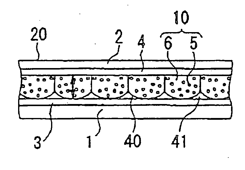
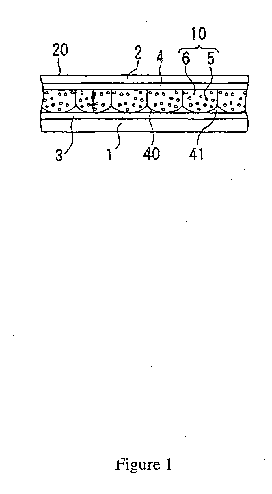
[0064]FIG. 1 is a cross-sectional view showing the structure of a first embodiment in which an electrophoretic device of the present invention is applied to an electrophoretic display device. As shown in the figure, an electrophoretic display device 20 of the present invention has a first substrate 1 and a second substrate 2, and the second substrate 2 side is used as an observer side. The second substrate 2 is formed of a light transmissive plate such as a transparent glass or a transparent film. On a surface of the second substrate 2 opposing the first substrate 1, a transparent electrode 4 film is formed. The transparent electrode 4 is formed, for example, of indium tin oxide (ITO) film.

[0065] Although being not always necessary to be transparent, the first substrate 1 is formed, for example, of a glass substrate or a film substrate. In addition, on a surface of the first substrate 1 opposing the second substrate 2, an electrode 3 is formed. Although being not always necessary t...

example 2

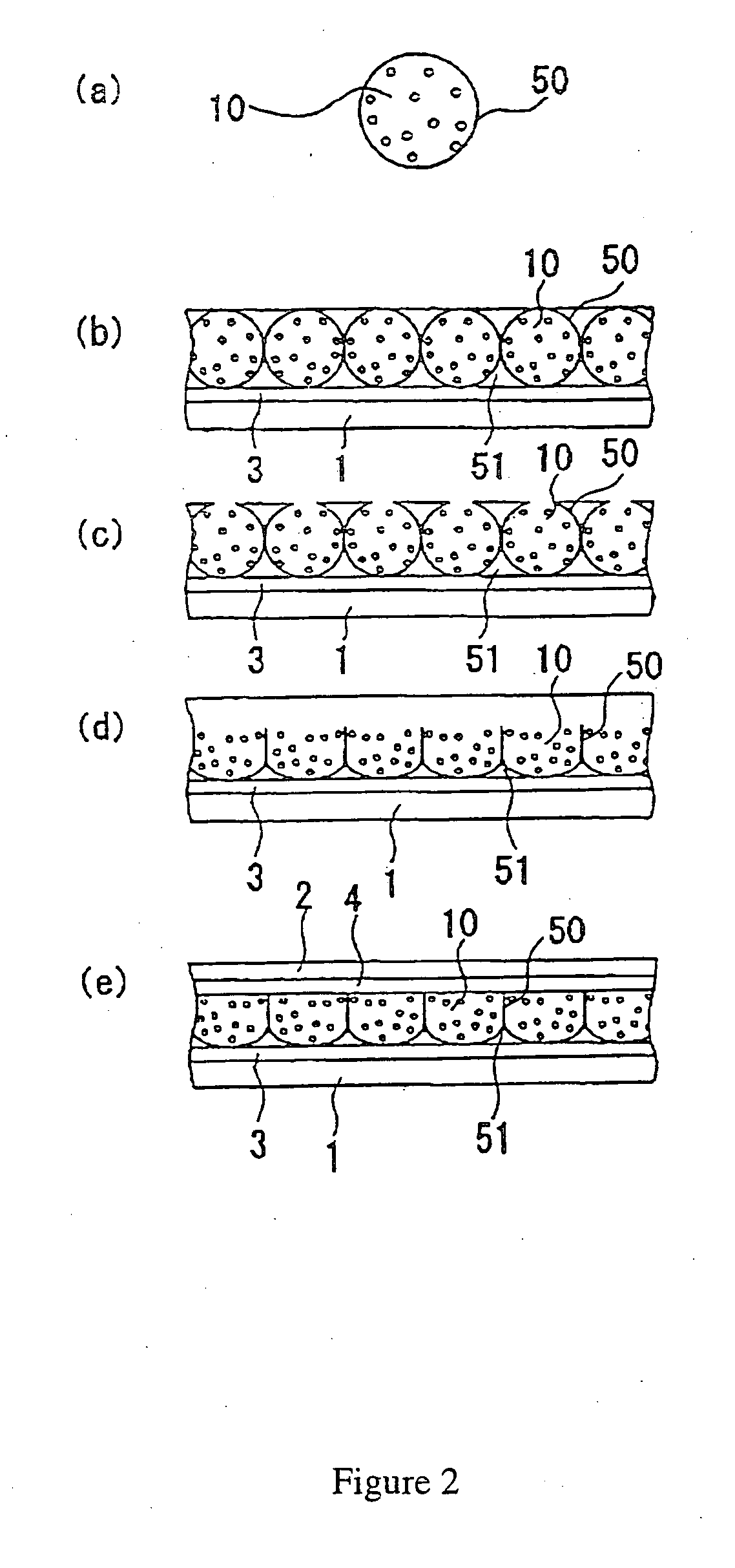
[0090] Next, a method for manufacturing an electrophoretic device according to a second embodiment of the present invention will be described. In the first embodiment, after the microcapsules 50 and the binding agent 51 are provided on the electrode 3, the opening-forming step for the wall films of the microcapsules and the contraction step for the binding agent 51 are performed, and the electrode 4 is then provided.

[0091] However, in this second embodiment, the microcapsules 50 and the binding agent 51 are accommodated beforehand between the electrodes 3 and 4, and in the state described above, the opening-forming step for the wall film of the microcapsule and the contraction step for the binding agent are performed. In this manufacturing method, the opening-forming technique may use heat, mechanical stress, light, sonic waves, or the like, and the contraction technique may use heat, mechanical stress, light, or the like.

[0092] According to this second embodiment, prior to the op...


PUM

PropertyMeasurementUnit
average volume particle diameteraaaaaaaaaa
particle diameteraaaaaaaaaa

Abstract

An electrophoretic display device of the present invention is formed of a first substrate, a second substrate, and microcapsules which are accommodated between these substrates and which contain an electrophoretic dispersion, wherein each of the microcapsules has an opening in at least a part thereof.

Description

[0001] This application is a divisional patent application of U.S. Ser. No. 10 / 224,635 filed Aug. 19, 2002, claiming priority to JP 2001-249561 filed Aug. 20, 2001 and JP 2002-236516 filed Aug. 14, 2002, all of which are hereby incorporated by reference.BACKGROUND OF THE INVENTION [0002] 1. Technical Field of the Invention [0003] The present invention relates to electrophoretic devices and manufacturing methods therefor, and more specifically, relates to an electrophoretic device in which an electrophoretic dispersion containing a dispersion medium and electrophoretic particles is accommodated between electrodes opposing each other. [0004] In addition, the present invention relates to various electronic apparatuses each provided with an electrophoretic display device incorporating the above electrophoretic device. [0005] 2. Description of the Related Art [0006] Hitherto, concerning electrophoretic devices in which an electrophoretic dispersion containing a dispersion medium and elec...

Claims


Application Information

Patent Timeline
Patent Type & Authority Applications(United States)
IPC IPC(8): G02B26/00G02F1/167G02F1/16757G02F1/1679
CPCG02F1/167G02F1/1679G02F1/16757
Inventor KAWAI, HIDEYUKI
Owner E INK CORPORATION
Why Eureka
Try Eureka