System and method for controlling demand of multi-air-conditioner

Inactive Publication Date: 2008-07-31
LG ELECTRONICS INC
View PDF20 Cites 55 Cited by
  • Summary
  • Abstract
  • Description
  • Claims
  • Application Information

AI Technical Summary

Benefits of technology

[0012]To achieve these and other advantages and in accordance with the purpose of the present invention, as embodied and broadly described herein, the present invention provides in one aspect a system for controlling multiple air conditioners. The system includes a demand control unit configured to divide the multiple air conditioners into groups, to assign a priority level to each group, to calculate an estimated power amount used by the multiple air conditioners based on an amount of power consumed by the multiple air conditioners during a predetermined time period, and to forcibly control an operation of one or more air conditioners include

Problems solved by technology

However, the related art control system does not take into account an individual's comfort.
Therefore, the related art air conditioner control system

Method used


Image

  • System and method for controlling demand of multi-air-conditioner
  • System and method for controlling demand of multi-air-conditioner
  • System and method for controlling demand of multi-air-conditioner

Examples


first embodiment

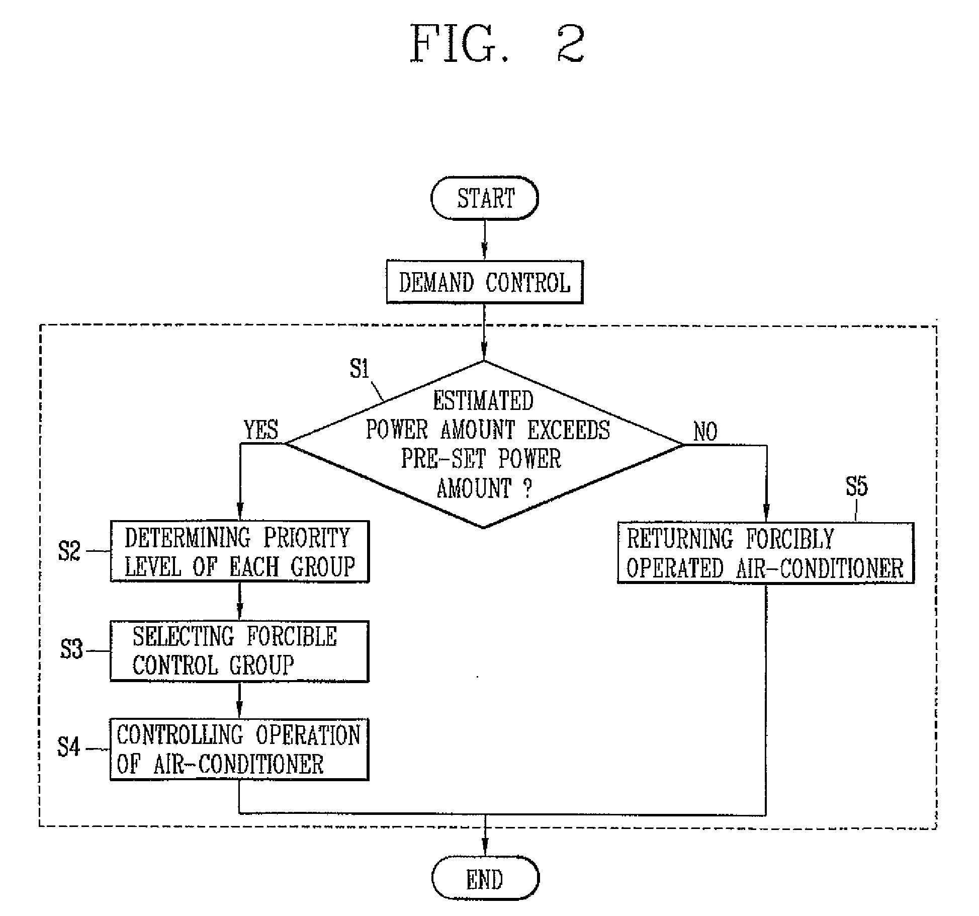
[0032]A method of controlling multiple air conditioners according to the present invention will now be described in more detail with reference to FIG. 2. FIG. 1 will also be referred to in this description.

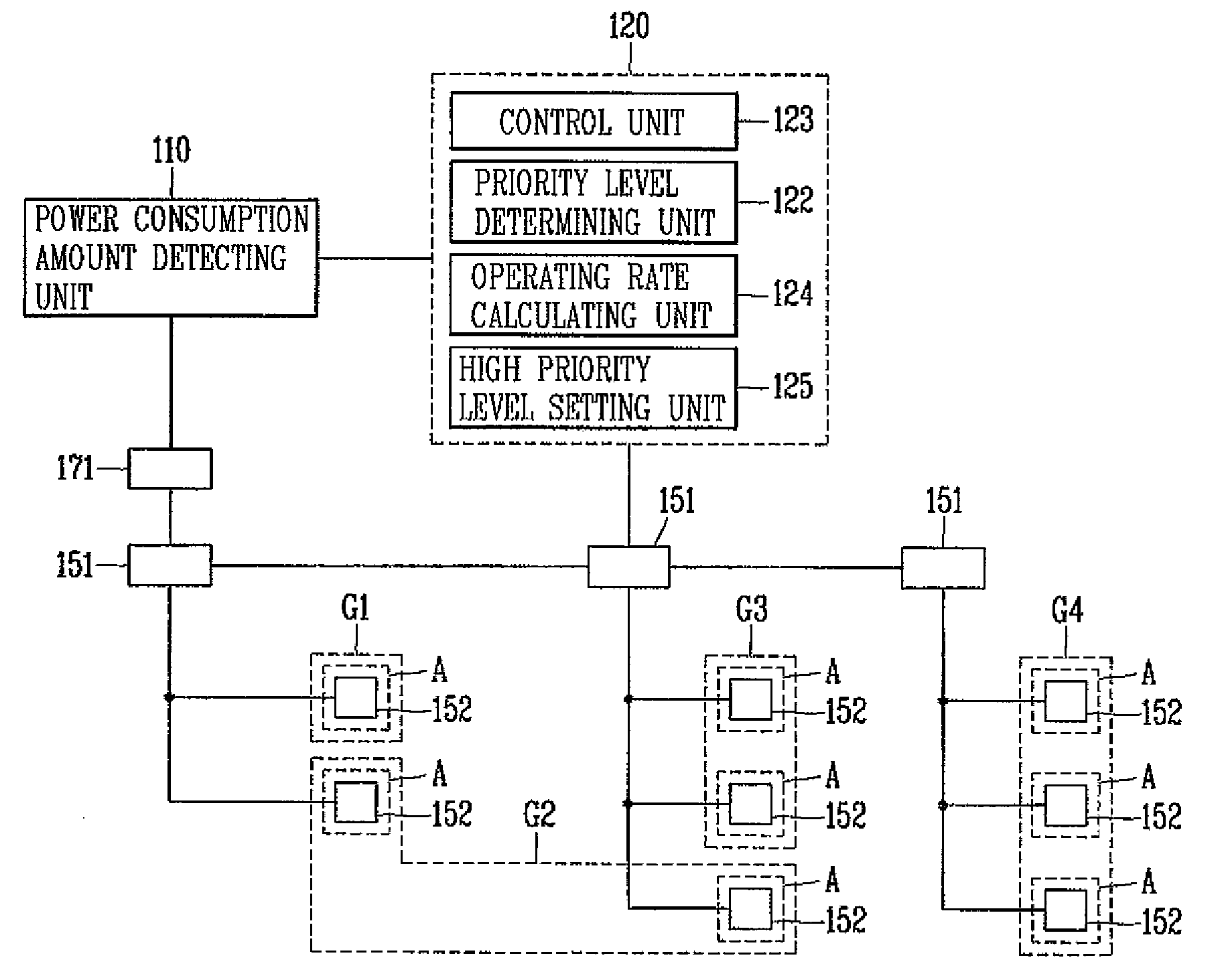
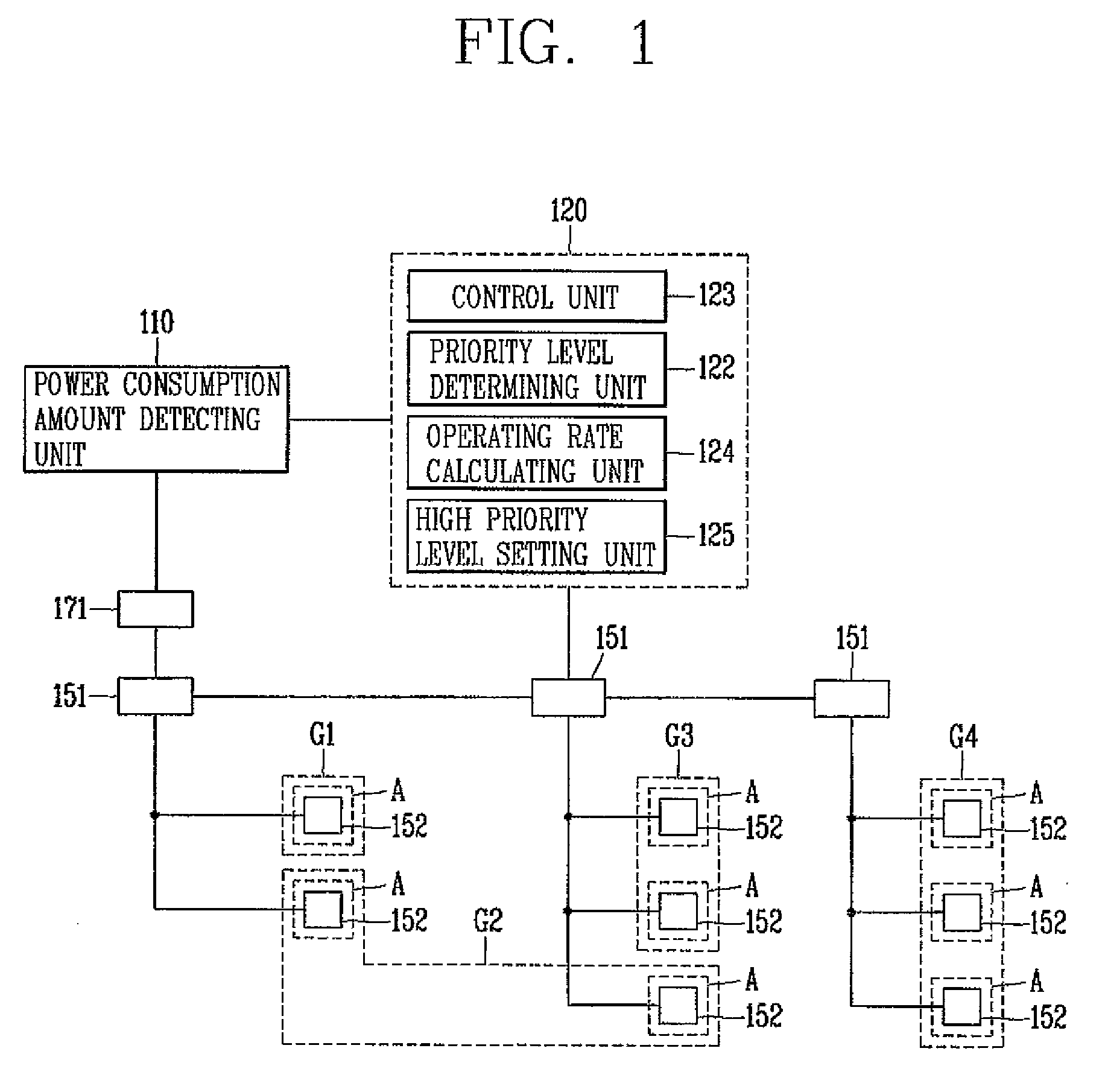
[0033]As discussed above, the multiple air conditioners are divided into groups G1, G2, G3 and G4, in which each group includes one or more indoor units 152. Further, each group is assigned a priority level. In addition, the groups may be divided and assigned priority levels by a manager of the building, automatically based on operating histories of the air conditioners, etc. The groups G1, G2, G3 and G4 may also be sequentially assigned a priority level (i.e., the group G1 is assigned a highest priority level, the group G2 is assigned the next highest priority level, etc.). That is, in accordance with embodiments of the present invention, the groups may be divided and assigned priority levels in a variety of different methods, which allows for the individual's comfort to be taken...

second embodiment

[0043]FIG. 3 illustrates a system for controlling multiple air conditioners according to the As shown in FIG. 3, the system includes a power consumption amount detecting unit 210, a demand control unit 220 and multiple air conditioners including outdoor units 251 and indoor units 252. Also shown is a power detecting unit (watt-hour meter) 271. Note that FIG. 3 is similar to FIG. 1, except that the demand control unit 220 includes a control history recording unit 225 in addition to a control unit 223, a priority level determining unit 222, an operating rate calculating unit 221, and a high priority level setting unit 224.

[0044]In more detail, the power consumption detecting unit 210 detects a power consumption amount of the multiple air conditioners installed in each area of a building using data supplied from the watt-hour meter 271 connected with the multiple air conditioners, and transfers the data to the demand control unit 220. The demand control unit 220 then detects whether t...

third embodiment

[0058]A system for controlling multiple air conditioners according to the present invention will now be described with reference to FIG. 5. As shown in FIG. 5, the system includes a power consumption amount detecting unit 310, a demand control unit 320 and multiple air conditioners including outdoor units 352 and indoor units 351. Also shown is a power detecting meter (watt / hr meter) 371 and temperature measuring units 361. Note that FIG. 5 is similar to FIG. 1, except that system includes the temperature measuring units 361, and the demand control unit 320 includes a temperature difference unit 321 in addition to a control unit 323, a priority level determining unit 322, an operating rate calculating unit 324 and a high priority level setting unit 325.

[0059]In more detail, and as shown in FIG. 5, the temperature difference measuring unit 321 is disposed in an area (A) where the indoor unit 352 is installed and measures the temperature of the area (A). The temperature comparing diff...


PUM


Abstract

A system for controlling multiple air conditioners. The system includes a demand control unit configured to divide the multiple air conditioners into groups, to assign a priority level to each group, to calculate an estimated power amount used by the multiple air conditioners based on an amount of power consumed by the multiple air conditioners during a predetermined time period, and to forcibly control an operation of one or more air conditioners included in a respective group based on the priority level assigned to the respective group.

Description

[0001]This application claims priority to Korean Application No. 10-2007-0008570, filed in Korea on Jan. 26, 2007, the entire contents of which is also hereby incorporated in its entirety.BACKGROUND OF THE INVENTION[0002]1. Field of the Invention[0003]The present invention relates to a system and method for controlling multiple air conditioners.[0004]2. Description of the Related Art[0005]An air conditioner system that is placed in a large office building generally includes multiple air conditioners placed throughout the building. The air conditioners are controlled to operate within a predetermined temperature. That is, when the temperature of a room is within an allowable range, the air conditioner is turned off. When the temperature of the room is not within an allowable range, the corresponding air conditioner is turned on. However, the related art control system does not take into account an individual's comfort.[0006]Therefore, the related art air conditioner control system me...

Claims


Application Information

Patent Timeline
IPC IPC(8): G05D23/00F24F11/02
CPCF24F3/06F24F11/006F24F2011/0075F24F2011/0064F24F2011/0047F24F11/30F24F2140/60F24F11/62F24F11/65F24F11/46F24F11/52F24F11/47F24F11/54
Inventor YOON, YOUNG-SOOYOUN, SANG-CHULJEON, DUCK-GU
Owner LG ELECTRONICS INC
Why Eureka
Try Eureka