
Diagnosing a radio frequency identification reader

a radio frequency identification and reader technology, applied in the direction of instruments, nuclear elements, digital computer details, etc., can solve the problems of no easy method of self-testing or self-diagnosis, failure to perform any diagnostics,

Inactive Publication Date: 2008-07-31
TOSHIBA GLOBAL COMMERCE SOLUTIONS HLDG
View PDF9 Cites 40 Cited by
  • Summary
  • Abstract
  • Description
  • Claims
  • Application Information

AI Technical Summary

Benefits of technology

The patent describes a way to test a device called a radio frequency identification reader. The reader sends a signal to a special tag and then compares it with an expected signal to see if it works properly. This way, the reader can be tested regularly to make sure it is always working correctly.

Problems solved by technology

However, no easy method of performing a self-test, or performing a self-diagnostic exists.
Consequently, users frequently fail to perform any diagnostics on the RFID readers, which ultimately results in undetected and un-repaired failures for unacceptably long periods of time.

Method used


Image

  • Diagnosing a radio frequency identification reader
  • Diagnosing a radio frequency identification reader
  • Diagnosing a radio frequency identification reader

Examples


Embodiment Construction

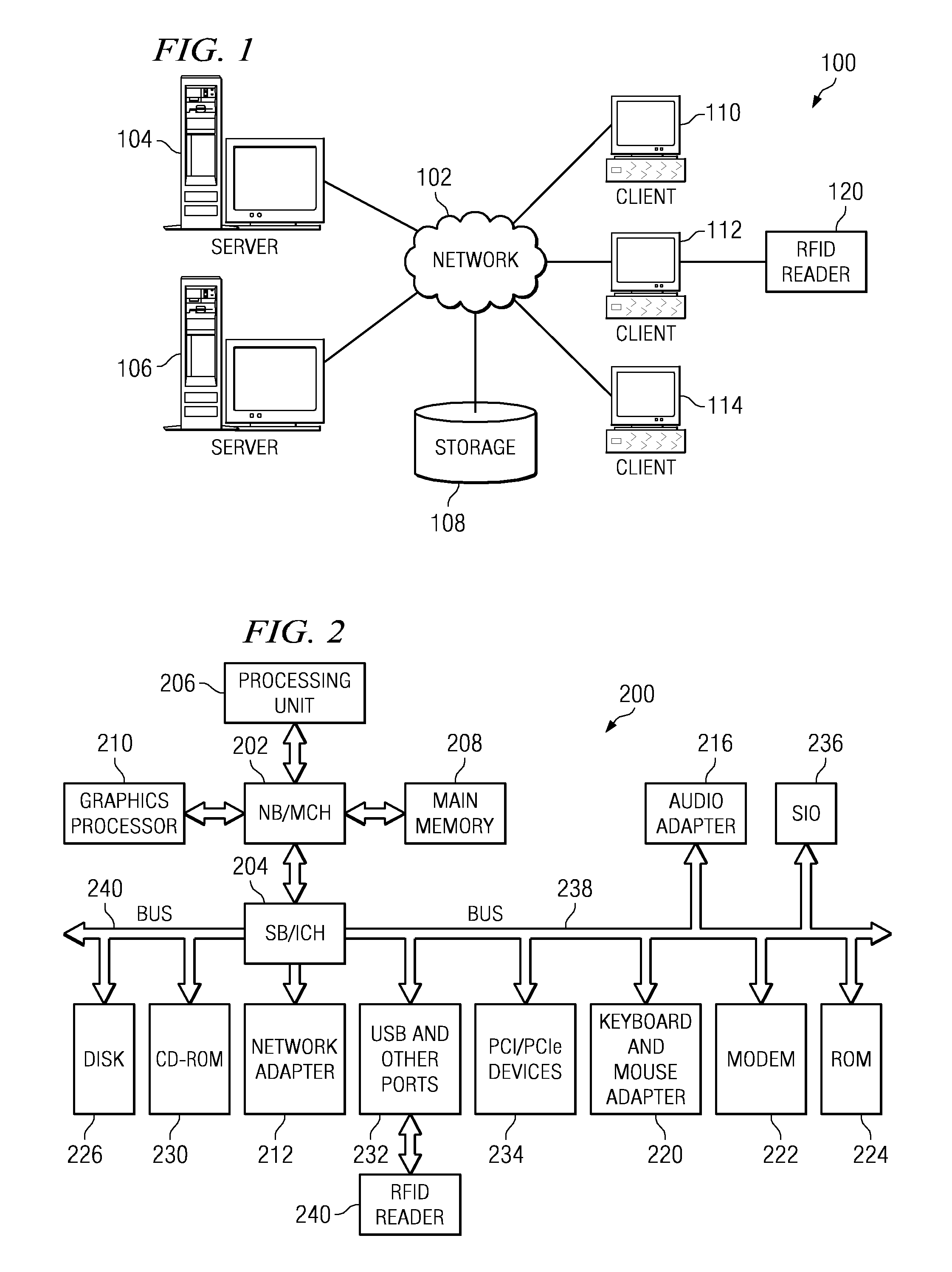
[0014]With reference now to the figures and in particular with reference to FIGS. 1-2, exemplary diagrams of data processing environments are provided in which illustrative embodiments may be implemented. It should be appreciated that FIGS. 1-2 are only exemplary and are not intended to assert or imply any limitation with regard to the environments in which different embodiments may be implemented. Many modifications to the depicted environments may be made.

[0015]With reference now to the figures, FIG. 1 depicts a pictorial representation of a network of data processing systems in which illustrative embodiments may be implemented. Network data processing system 100 is a network of computers in which embodiments may be implemented. Network data processing system 100 contains network 102, which is the medium used to provide communications links between various devices and computers connected together within network data processing system 100. Network 102 may include connections, such ...


PUM


Abstract

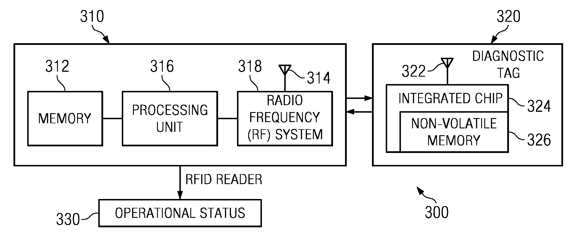
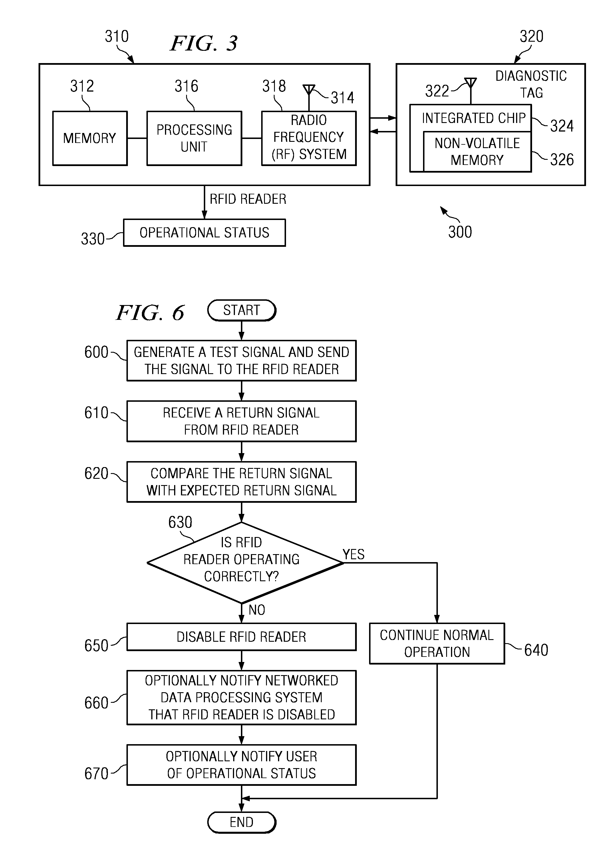
The illustrative embodiments provide a computer implemented method, an apparatus, and a computer program product for testing a radio frequency identification reader. The radio frequency identification reader transmits a test signal to a diagnostic tag during a diagnostic period. Responsive to receiving a return signal from the diagnostic tag, the radio frequency identification reader compares the return signal with an expected return signal to form a comparison. The radio frequency identification reader identifies an operational status for the radio frequency identification reader using the comparison.

Description

BACKGROUND OF THE INVENTION[0001]1. Field of the Invention[0002]The present invention relates generally to an improved radio frequency identification reader. Specifically, the present invention relates to a computer implemented method, an apparatus, and a computer program product for testing a radio frequency identification reader.[0003]2. Description of the Related Art[0004]Radio frequency identification (RFID) systems are widely used in industry to automatically identify a product, animal, or person. RFID systems typically include a detector or reader, and a number of transponders or tags. Presently, RFID systems do not include a mechanism to self-test, or to perform a complete self-diagnosis. Current methods exist to determine whether an RFID reader can identify multiple transponders, or tags that are in close proximity to each other. However, no easy method of performing a self-test, or performing a self-diagnostic exists.[0005]Current methods for testing the operability of a RF...

Claims


Application Information

Patent Timeline
Patent Type & Authority Applications(United States)
IPC IPC(8): G01R31/02
CPCG06K7/0095G01R31/2822
Inventor CATO, ROBERT THOMASDO, PHUC KYPIERCE, JUSTIN MONROE
Owner TOSHIBA GLOBAL COMMERCE SOLUTIONS HLDG
Learn More