
Pollutant Trap

a pollution trap and pollution technology, applied in sedimentation settling tanks, liquid displacement, separation processes, etc., can solve the problems of major source of water pollution, no treatment,

Inactive Publication Date: 2008-08-07
IMBRIUM SYST
View PDF9 Cites 15 Cited by
  • Summary
  • Abstract
  • Description
  • Claims
  • Application Information

AI Technical Summary

Benefits of technology

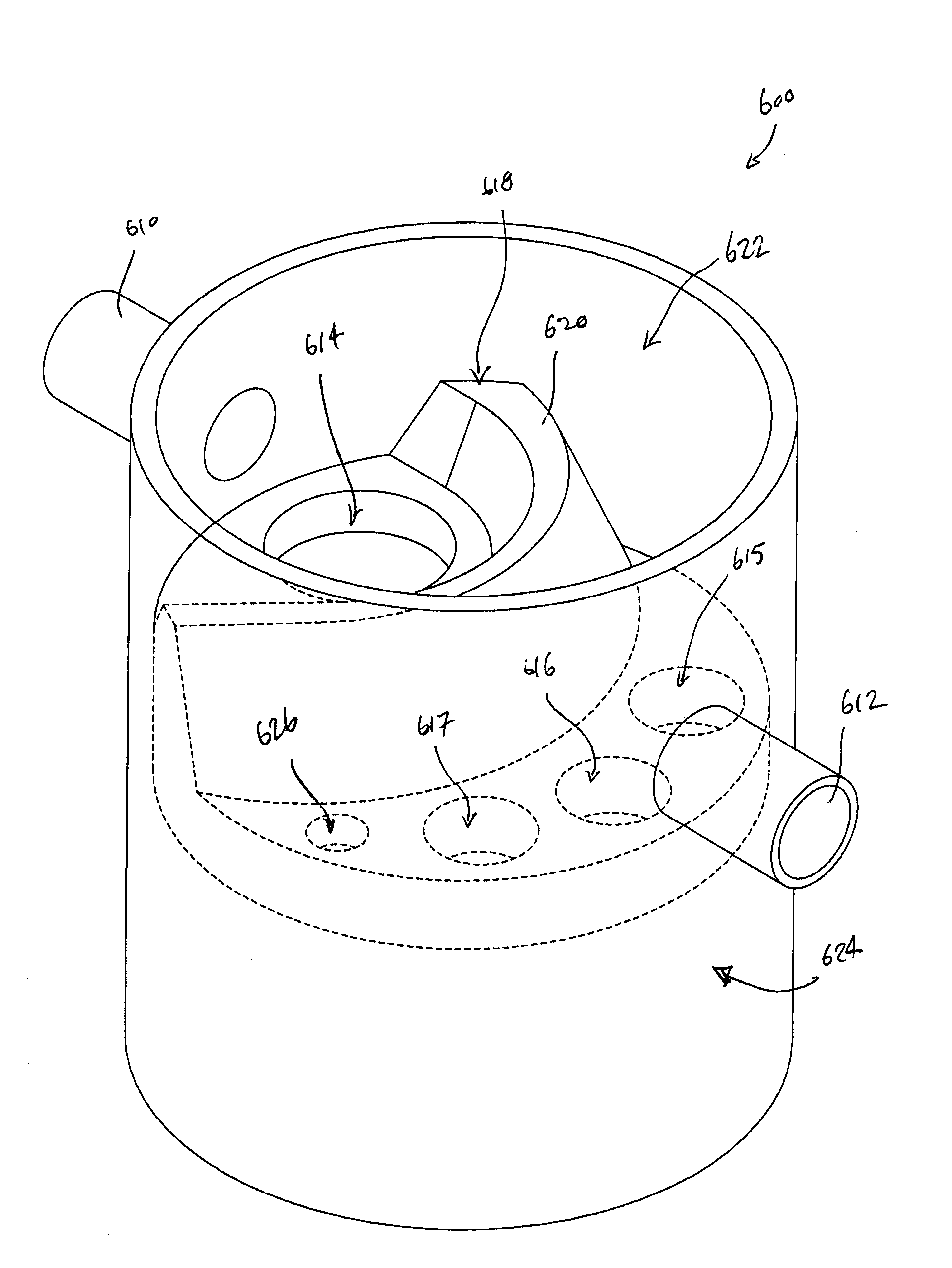
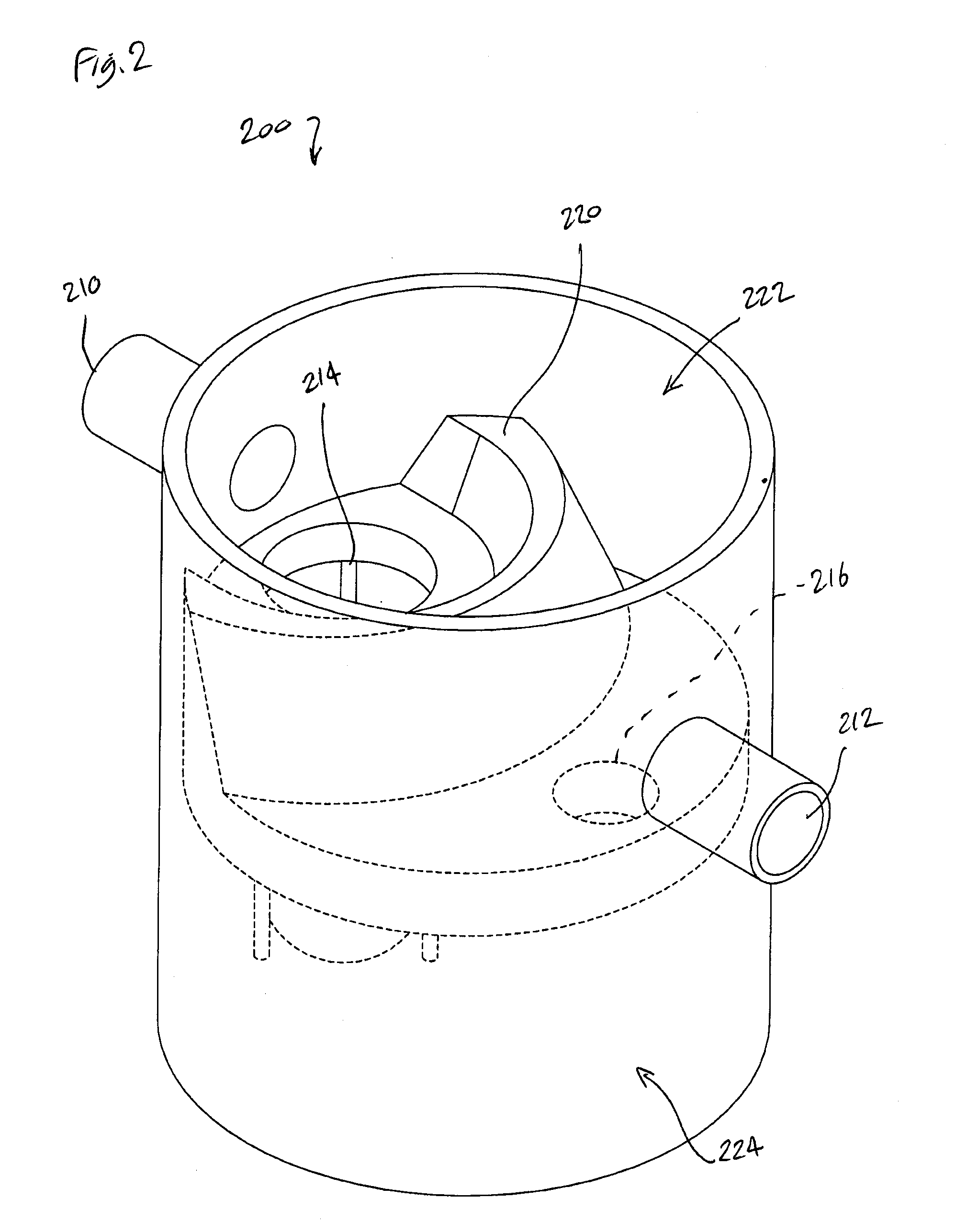
[0007]In another aspect, there is provided an insert for removing pollutants from a polluted liquid. The insert includes an inlet opening and a plurality of outlet openings formed through the insert. The inlet opening is positioned at a first elevation and each of the plurality of outlet openings is positioned at a second elevation, the first elevation being greater than the second elevation. The insert also has a weir having an elevated ...

Problems solved by technology

Stormwater runoff often does not receive any treatment before it enters streams, lakes, and other surface waters, and it is a major source of water pollution.

Method used


Image

  • Pollutant Trap
  • Pollutant Trap
  • Pollutant Trap

Examples


Embodiment Construction

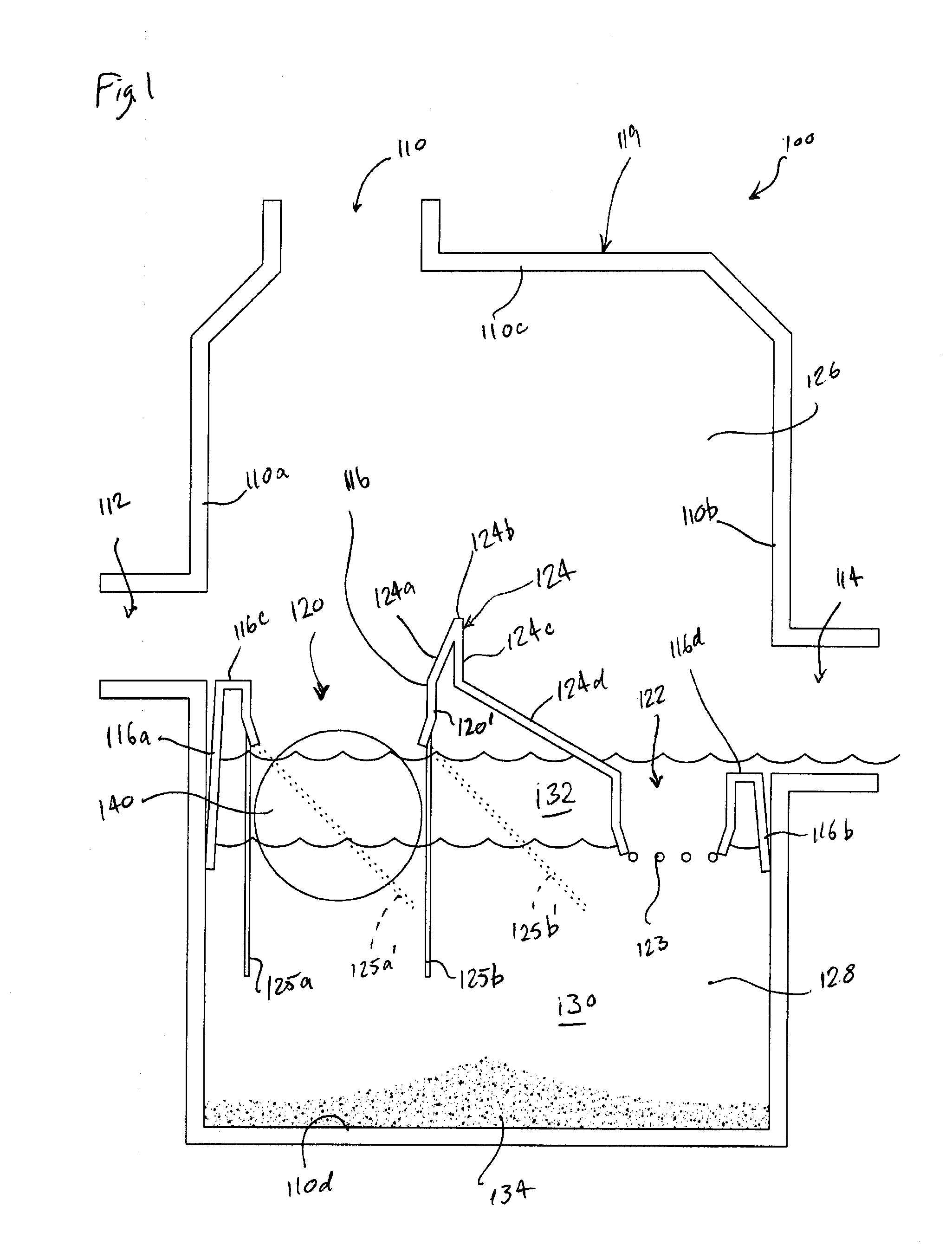
[0020]FIG. 1 is a cross-sectional side view of a gross pollutant trap having an insert and float in accordance with an exemplary embodiment of the present invention. The gross pollutant trap 100 includes a tank 119 having a dividing wall, such as an insert 116, and a float 140. The insert 116 is disposed within the tank 119 and the float 140 is located under the insert 116 and within the tank 119.

[0021]In some embodiments, the tank 119 may be a chamber having as its boundaries a first interior side wall 110a, a second interior side wall 110b opposite the first interior side wall 110a, a top interior wall 110c and a bottom interior wall 110d opposite the top interior wall 110c. In various embodiments, the first interior side wall 110a, second interior side wall 110b, top interior wall 110c and bottom interior wall 110d may be formed of concrete. For example, they may be formed as pre-cast concrete. In various other embodiments, any suitable material may be used as is well-known to th...


PUM

PropertyMeasurementUnit
Angleaaaaaaaaaa
Shapeaaaaaaaaaa
Dimensionaaaaaaaaaa

Abstract

A system for removing pollutants from a liquid. The system has a tank with a bypass chamber, a treatment chamber, inlet and outlet ports. A dividing wall is located within the tank and defines the bypass chamber and the treatment chamber. The dividing wall has an inlet opening, one or more outlet openings, retaining rods forming a retention space at least partially below the inlet opening, and a vertically-extending weir between the inlet opening and the outlet opening(s). The inlet opening receives polluted liquid from the inlet port and the one or more outlet openings output a cleaned liquid to the outlet port. A float in the treatment chamber is adapted to float in a retention space formed by the retaining rods. The float is adapted to rise against the inlet opening when a fluid level in the treatment chamber reaches a predetermined level to substantially block the inlet opening.

Description

CROSS REFERENCE TO RELATED APPLICATIONS[0001]The present invention claims priority to U.S. Provisional Application Ser. No. 60 / 887,745, filed on Feb. 1, 2007, and U.S. Provisional Application Ser. No. 61 / 021,425, filed on Jan. 16, 2008, the contents of both of which are incorporated herein by reference in their entirety.FIELD OF THE INVENTION[0002]The present invention relates to water treatment systems, in general, and gross pollutant traps for a water treatment system, in particular.BACKGROUND OF THE INVENTION[0003]Liquids such as stormwater runoff and snow melt travel over the ground or impervious surfaces—e.g., roofs of buildings, homes and sheds, roadways, parking lots, sidewalks and driveways—and drain into natural or manmade drainage ways. In some cases, such runoff drains directly into bodies of water. Stormwater runoff often does not receive any treatment before it enters streams, lakes, and other surface waters, and it is a major source of water pollution. For example, var...

Claims


Application Information

Patent Timeline
IPC IPC(8): B01D21/34B01D21/28
CPCB01D21/0003B01D21/0024E03F5/16B01D21/307B01D2221/02B01D21/0036B01D21/0006B01D21/34
Inventor MURRAY, CHRISTOPHER ADAMMONTEITH, SCOTT GORDON
Owner IMBRIUM SYST
Learn More