Mobile equipment with display function

Active Publication Date: 2008-08-07
PENTAX RICOH IMAGING CO LTD
View PDF22 Cites 41 Cited by
  • Summary
  • Abstract
  • Description
  • Claims
  • Application Information

AI Technical Summary

Benefits of technology

[0006]An object of the present invention is to provide mobile equipment that is capable of effectively displaying information related to the image editing process while allowing free editing of the entirety of a displayed image.

Problems solved by technology

Since mobile equipment has very limited display are, the user cannot write or draw freely over an entire image.

Method used


Image

  • Mobile equipment with display function
  • Mobile equipment with display function
  • Mobile equipment with display function

Examples


Embodiment Construction

[0018]Hereinafter, the preferred embodiment of the present invention is described with reference to the attached drawings.

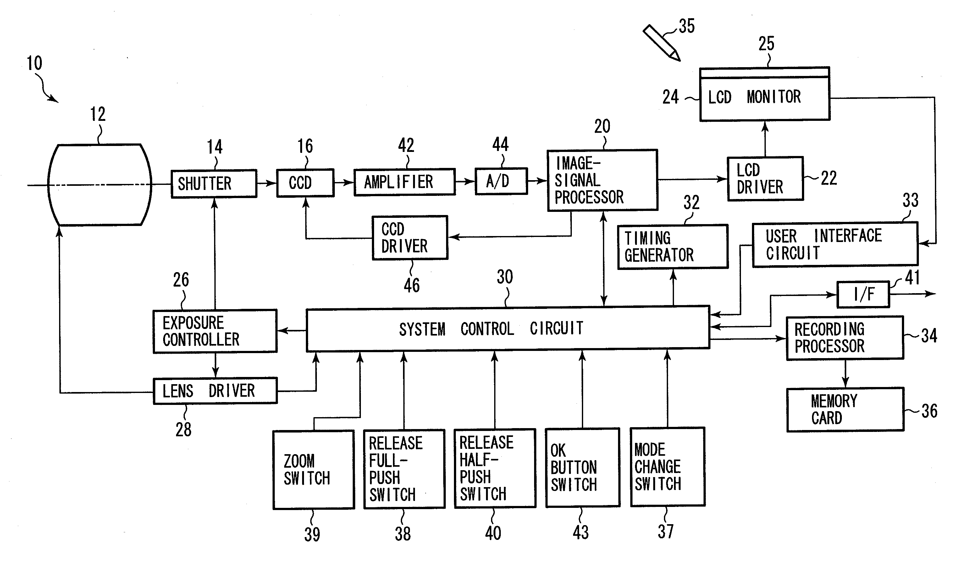
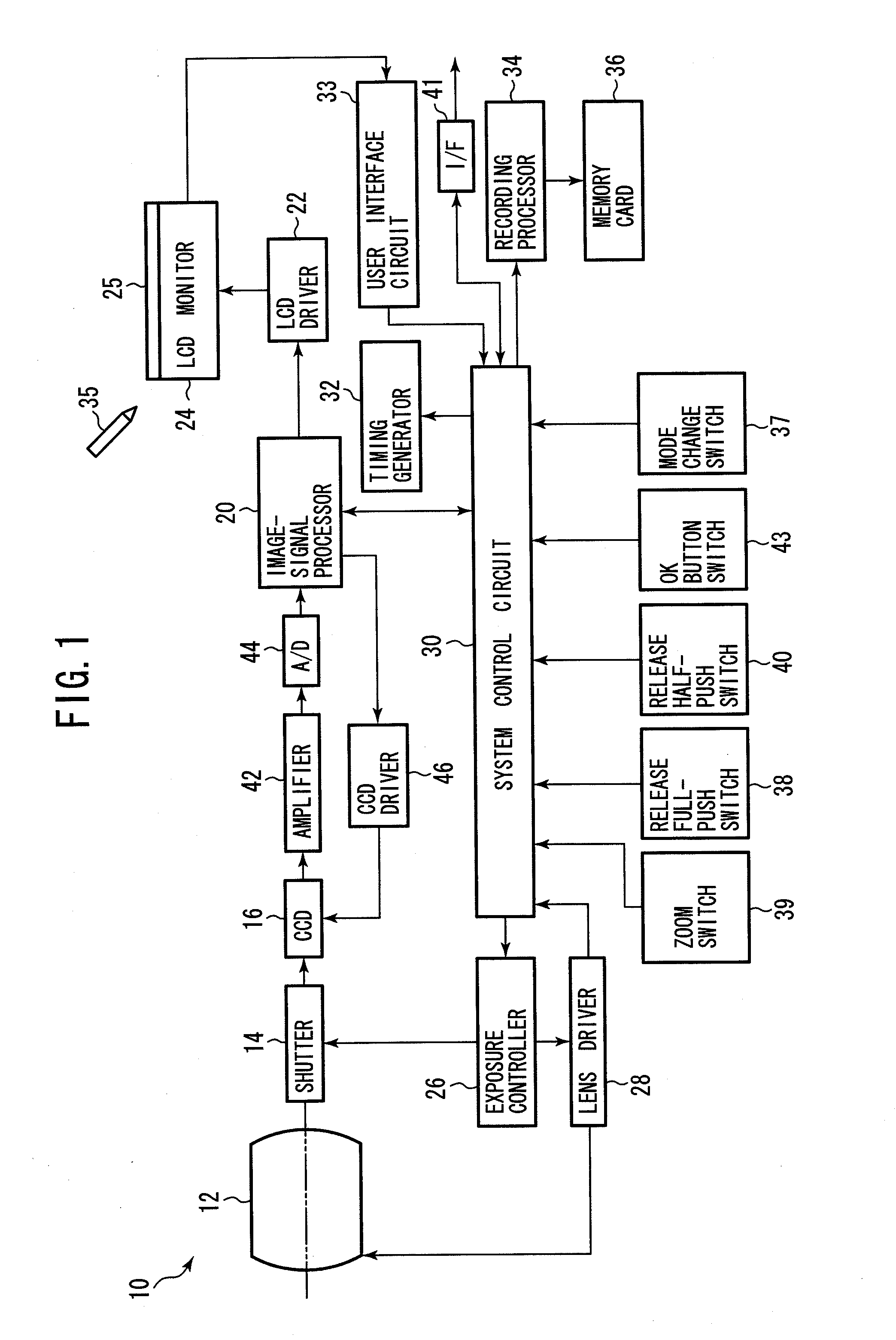
[0019]FIG. 1 is a block diagram of a digital camera according to the present embodiment.

[0020]The digital camera 10 is a compact camera, and a memory card 36 is removably installed into the camera 10. The camera 10 has a system control circuit 30, which includes a CPU, a ROM unit and a RAM unit, and controls the action of the camera 10. The system control circuit 30 connects to a zoom switch 39, a release half-push switch 40, a release full-push switch 38, and an OK button switch 43, and detects an operation signal when the release button, zoom lever, or OK button (not shown) is operated by the user.

[0021]Also, the camera 10 has a mode-change button (not shown) for switching mode between the photographing mode and the playback mode. The system control circuit 30 detects a signal from a mode-change switch 37. When the main power button (not shown) is turned on, a ...


PUM


Abstract

A piece of mobile equipment has a display processor that displays an image and at least one icon on a screen, and a touch-sensitive device disposed on said screen. The display processor displays input information in accordance with an input operation to said touch-sensitive device, and removes the icon on the screen in accordance with the input operation.

Description

BACKGROUND OF THE INVENTION[0001]1. Field of the Invention[0002]The present invention relates to mobile electronic equipment, such as digital cameras, cell phones, PDAs (Personal Digital Assistants), and image viewers, that is capable of displaying characters and drawings together with an image. In particular, it relates to an image-editing process.[0003]2. Description of the Related Art[0004]In mobile equipment with image editing functions, characters and drawings may be superimposed on a displayed image by the user's input operation, and the edited image is recorded or printed out. For example, a touch screen is provided on an LCD monitor as an input device, and the user writes and draws on the touch screen using a stylus. Usually, a tool bar, composed of a series of icons, is displayed on the monitor so that the user can select a line type, stamp type, etc., by touching a given icon with the stylus. The display area of the toolbar grows as editing functions increase, so that the ...

Claims


Application Information

Patent Timeline
IPC IPC(8): G06F3/041G06F3/0481G06F3/0482G06F3/0488
CPCG06F3/0488G06F3/04817G06F3/0412G06F3/04845
Inventor SHIMIZU, SAKI
Owner PENTAX RICOH IMAGING CO LTD
Why Eureka
Try Eureka