Controller having function for displaying motor load

a technology of motor load and controller, which is applied in the field of controller, can solve the problems of difficult to covert one load meter value, difficult to simultaneously determine both load meter values, and operator's inability to know whether the motor can be continuously operated at the present load, etc., and achieve the effect of effective display of information

Active Publication Date: 2016-11-08
FANUC LTD
View PDF14 Cites 1 Cited by
  • Summary
  • Abstract
  • Description
  • Claims
  • Application Information

AI Technical Summary

Benefits of technology

[0013]An object of the present invention is to provide a low-cost controller having a function for effectively displaying information of present motor output regarding the maximum output and the continuous rating output of the motor, even when the base velocities of the maximum output characteristic and the continuous rating output characteristic are different.

Problems solved by technology

Therefore, it is not easy to covert one load meter value to the other load meter value.
In other words, in a motor as shown in FIG. 9, it is necessary to take into consideration the present motor velocity (or the motor velocity during processing) in order to convert one load meter value to the other load meter value, and thus it is difficult to simultaneously determine both of the load meter values.
However, in a motor having a characteristic as shown in FIG. 9, even when the load meter value with reference to the maximum output is given, an operator cannot easily know as to whether the motor can be continuously operated at the present load (or how much margin is left between the motor output and the continuous rating output).
However, this document does not provide means to solve the above problem.
Therefore, the method of JP H10-090011 A is disadvantageous in view of a graphic resource, a memory resource and a cost of the controller.

Method used


Image

  • Controller having function for displaying motor load
  • Controller having function for displaying motor load
  • Controller having function for displaying motor load

Examples


Embodiment Construction

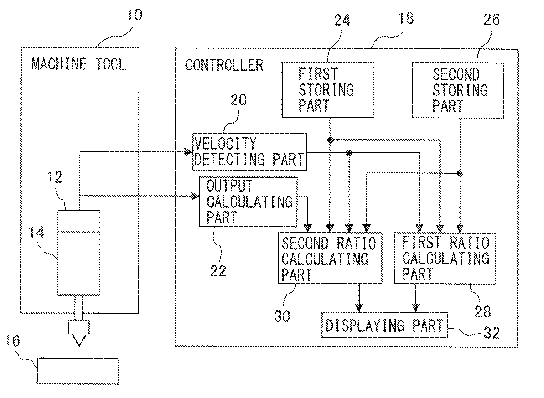
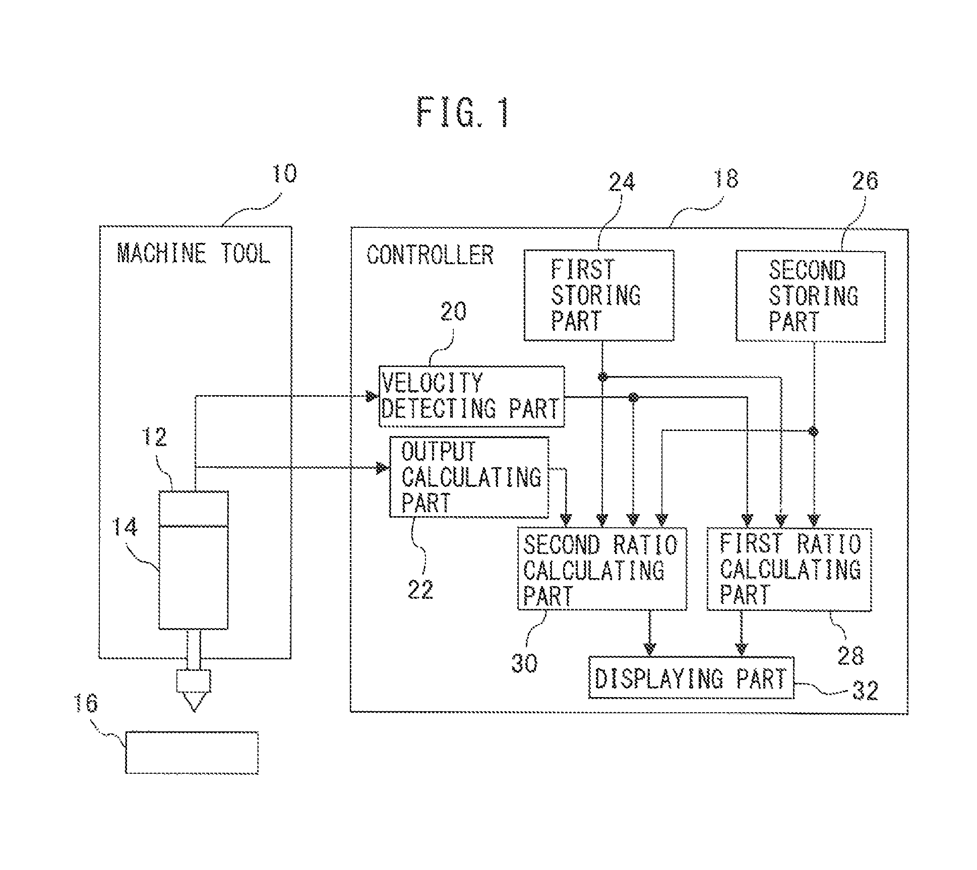
[0027]FIG. 1 shows a functional block diagram of a controller according to a preferred embodiment of the present invention, along with a schematic configuration of a machine tool having a motor (or an electric motor) controlled by the controller. Machine tool 10 has a spindle 14 driven by a schematically shown motor 12, so that machine tool 10 can carry out processing such as cutting in relation to workpiece 16. Motor 12 is controlled by a controller 18. Controller 18 has a velocity detecting part 20 which detects a rotation frequency (or a number of rotations) of motor 12, and an output calculating part 22 which calculates an output of motor 12, wherein controller 18 controls motor 12 based on the present (for example, at the time of operation) rotation frequency and the present actual output, etc. In this regard, an encoder for detecting the rotating velocity (or the rotation frequency) of motor 12 may be used as velocity detecting part 20. However, a detection value detected by v...


PUM

PropertyMeasurementUnit
rotation frequencyaaaaaaaaaa
torqueaaaaaaaaaa
velocityaaaaaaaaaa

Abstract

A low-cost controller having a function for effectively displaying information of present motor output regarding the maximum output and the continuous rating output of the motor. The controller includes first and second storing parts which store first and second data, representing a relationship between a rotation frequency and a maximum output of the motor, and a relationship between the rotation frequency and a continuous rating output of the motor, respectively; first and second ratio calculating parts which calculate first and second ratios, corresponding to a ratio of one of the maximum output and the continuous rating output to the other at a present rotation frequency, and a ratio of a present actual output of the motor to the one of the maximum output and the continuous rating output at the present rotation frequency, respectively; and a displaying part which displays the first and second ratios on the same screen.

Description

RELATED APPLICATIONS[0001]The present application claims priority to Japanese Application Number 2013-177047, filed Aug. 28, 2013, the disclosure of which is hereby incorporated by reference herein in its entirety.BACKGROUND OF THE INVENTION[0002]1. Field of the Invention[0003]The present invention relates to a controller for controlling a motor which drives a spindle of a machine tool, the controller having a function for displaying motor load.[0004]2. Description of the Related Art[0005]In a machine tool having a spindle driven by a motor, a device for displaying motor load (or a load meter) is generally used, in order to judge or estimate whether processing under a certain processing condition such as a cutting condition can be carried out. For example, JP S58-120455 A discloses a device for displaying a ratio of a spindle load relative to a rated load, wherein the ratio is indicated in green when the ratio is not more than 100%, and the ratio is indicated in red when the ratio e...

Claims


Application Information

Patent Timeline
Patent Type & Authority Patents(United States)
IPC IPC(8): B23Q5/12F16H61/02G01L3/24G01D7/02B23Q5/10H02P29/00B23Q17/00
CPCB23Q5/12F16H61/0204G01L3/24B23Q5/10G01D7/02B23Q15/08
Inventor MORITA, YUUKI
Owner FANUC LTD
Why Eureka
Try Eureka