Cyclone separating apparatus for vacuum cleaner

a vacuum cleaner and separating apparatus technology, applied in the field of vacuum cleaners, can solve the problems of reducing the efficiency of separating contaminant, unable to effectively remove fine contaminants from air, and reducing the centrifugal force developed, so as to achieve high contaminant separating efficiency

Inactive Publication Date: 2008-08-14
SAMSUNG GWANGJU ELECTRONICS CO LTD
View PDF81 Cites 200 Cited by
  • Summary
  • Abstract
  • Description
  • Claims
  • Application Information

AI Technical Summary

Benefits of technology

[0017]The present invention has been developed in order to overcome the above drawbacks and other problems associated with the conventional arrangement. An aspect of the present invention is to provide a cyclone separating apparatus for a vacuum cleaner that has a high contaminant separating efficiency.

Problems solved by technology

However, such conventional apparatuses cannot effectively remove fine contaminants from air.
Thus, the collected contaminants impede the whirling of the air and therefore reduce the centrifugal force developed which reduces contaminant separating efficiency.

Method used


Image

  • Cyclone separating apparatus for vacuum cleaner
  • Cyclone separating apparatus for vacuum cleaner
  • Cyclone separating apparatus for vacuum cleaner

Examples


first embodiment

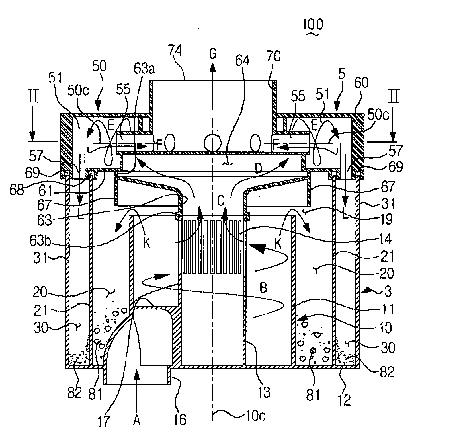
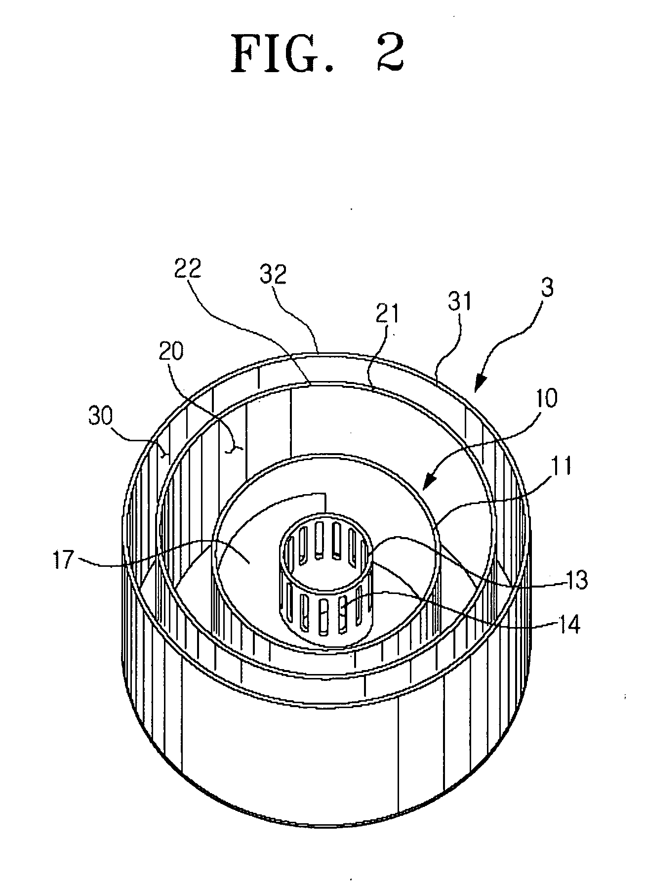
[0033]Referring to FIG. 1, a cyclone separating apparatus 100 for a vacuum cleaner according to the present invention may include a first cyclone unit 3 and a second cyclone unit 5.

[0034]The first cyclone unit 3 may be provided with a first cyclone 10, a first contaminants chamber 20, and a second contaminants chamber 30. The first cyclone 10 separates relatively large contaminants from drawn-in air. Air enters a lower portion of the first cyclone 10, and after contaminants are separated from the air, air may then be discharged through an upper portion of the first cyclone 10. Relatively large contaminants separated from air move in a direction against gravity.

[0035]The first cyclone 10 may be formed in a substantially hollow cylindrical shape with an inner wall 11. The inner wall 11 may have an open top and a bottom closed by a bottom plate 12. A first air entering pipe 16 may be disposed in the bottom plate 12. The first air entering pipe 16 may form a first air entrance. The firs...

second embodiment

[0057]Referring to FIG. 6, a cyclone separating apparatus 200 for a vacuum cleaner according to the present invention is shown. The cyclone separating apparatus 200 may include a first cyclone unit 203 and a second cyclone unit 205.

[0058]The first cyclone unit 203 may include a first cyclone 10, a first contaminants chamber 20, and a second contaminants chamber 30. The first cyclone unit 203 is substantially the same as the first cyclone unit 3 of the cyclone separating apparatus 100 for a vacuum cleaner according to the first embodiment of the present invention. Therefore, a detailed description thereof will be omitted.

[0059]The second cyclone unit 205 may include a plurality of second cyclones 210, a discharging air gathering member 230, and a housing 220.

[0060]The plurality of second cyclones 210 may be disposed downstream of the first cyclone 10. The plurality of second cyclones 210 may separate fine contaminants from air that has been discharged from the first cyclone 10. Each ...

third embodiment

[0066]In the cyclone separating apparatus 300 according to the present invention, air discharged from a plurality of second cyclones 50 may be gathered by the discharging air gathering member 330. The air may then be discharged below the first cyclone unit 303 through the second air discharging pipe 332.

[0067]The second air discharging pipe 332 may be formed integrally with the discharging air gathering member 330, as described above. Alternatively, the second air discharging pipe 332 may be formed integrally with the bottom plate 12 inside the first air discharging pipe 13. The second air discharging pipe 332 may be further provided with a top end (not illustrated) detachably connected with a bottom end (not illustrated) of the discharging air gathering member 330 similar to the first air discharging pipe 13. The second air discharging pipe 332 may be formed so that when the second cyclone unit 205 is mounted on the first cyclone unit 303, the second air discharging pipe 332 can be...


PUM

PropertyMeasurementUnit
shapeaaaaaaaaaa
cylindrical shapeaaaaaaaaaa
transparentaaaaaaaaaa

Abstract

A cyclone separating apparatus for a vacuum cleaner includes a first cyclone with an air entrance disposed on a lower portion of the first cyclone and an air exit disposed at an upper portion of the first cyclone; a first contaminants chamber substantially enclosing the first cyclone to collect contaminants discharged from the first cyclone; a plurality of second cyclones above the first cyclone, the plurality of second cyclones being substantially perpendicular to a center axis of the first cyclone; and a second contaminants chamber disposed outside the first contaminants chamber to collect contaminants discharged from the plurality of second cyclones.

Description

CROSS-REFERENCES TO RELATED APPLICATIONS[0001]This application claims the benefit under 35 U.S.C. §119(a) from Korean Patent Application No. 2007-15478 filed Feb. 14, 2007 in the Korean Intellectual Property Office, the disclosure of which is incorporated herein by reference in its entirety.[0002]This application may be related to the copending U.S. patent application Ser. No. 10 / 840,248, filed May 7, 2004 entitled “Cyclone Separating Apparatus and a Vacuum Cleaner Having the Same” by Jang-Keun Oh et al., the entire disclosure of which is incorporated herein by reference.[0003]This application may be related to the copending U.S. patent application Ser. No. 10 / 840,230, filed May 7, 2004 entitled “Cyclone Separating Apparatus and a Vacuum Cleaner Having the Same” by Jang-Keun Oh et al., the entire disclosure of which is incorporated herein by reference.[0004]This application may be related to the copending U.S. patent application Ser. No. 10 / 840,231, filed May 7, 2004 entitled “Cyclo...

Claims


Application Information

Patent Timeline
Patent Type & Authority Applications(United States)
IPC IPC(8): B01D45/12
CPCA47L9/1625A47L9/1641A47L9/1683A47L9/1658A47L9/165Y10S55/03A47L9/16
Inventor OH, JANG-KEUNCHA, SEUNG-YONG
Owner SAMSUNG GWANGJU ELECTRONICS CO LTD
Why Eureka
Try Eureka