Stepping motor and system thereof

a technology of stepping motor and stepping motor, which is applied in the direction of dynamo-electric converter control, instruments, horology, etc., can solve the problems of increasing the cost the total size of the stepping motor becomes large, and the phenomenon of step-out may occur, so as to achieve the effect of low material cost and small siz

Inactive Publication Date: 2015-03-19
SAMSUNG ELECTRONICS CO LTD
View PDF3 Cites 13 Cited by
  • Summary
  • Abstract
  • Description
  • Claims
  • Application Information

AI Technical Summary

Benefits of technology

[0010]The present disclosure has been developed in order to overcome the above drawbacks and other problems associated with the conventional arrangement. An aspect of the present disclosure is related to a stepping motor and a stepping motor system that are small in size and have a low material cost compared to the conventional stepping motor that uses an optical encoder or a magnetic encoder, by configuring the stepping motor and the stepping motor system to detect a step-out phenomenon by installing a sensor portion capable of detecting a magnetic force inside a housing.

Problems solved by technology

However, the stepping motor is weak to the inertial load and, when the stepping motor is driven at high load and high speed, a step-out phenomenon may occur.
However, there is a problem that, when an optical encoder or a magnetic encoder is attached to the stepping motor, a total size of the stepping motor becomes large due to the size of the optical encoder or the magnetic encoder attached to the outside of the stepping motor.
Furthermore, there is a problem that the cost of the stepping motor is increased due to the price of the optical encoder or the magnetic encoder.

Method used


Image

  • Stepping motor and system thereof
  • Stepping motor and system thereof
  • Stepping motor and system thereof

Examples


Embodiment Construction

[0039]Hereinafter, certain exemplary embodiments of the present disclosure will be described in detail with reference to the accompanying drawings.

[0040]The matters defined herein, such as a detailed construction and elements thereof, are provided to assist in a comprehensive understanding of this description. Thus, it is apparent that exemplary embodiments may be carried out without those defined matters. Also, well-known functions or constructions are omitted to provide a clear and concise description of exemplary embodiments. Further, dimensions of various elements in the accompanying drawings may be arbitrarily increased or decreased to assist in a comprehensive understanding.

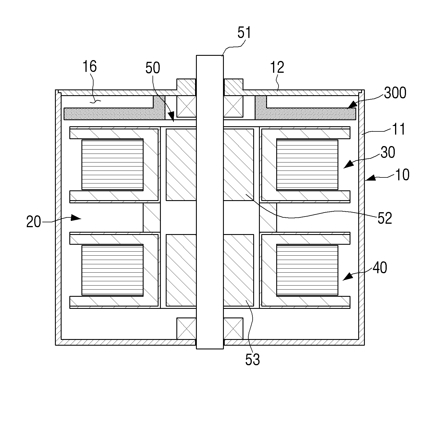
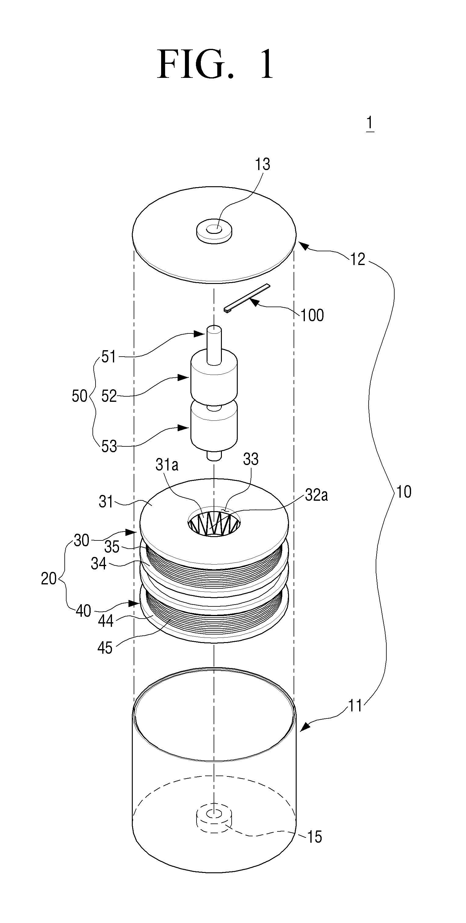
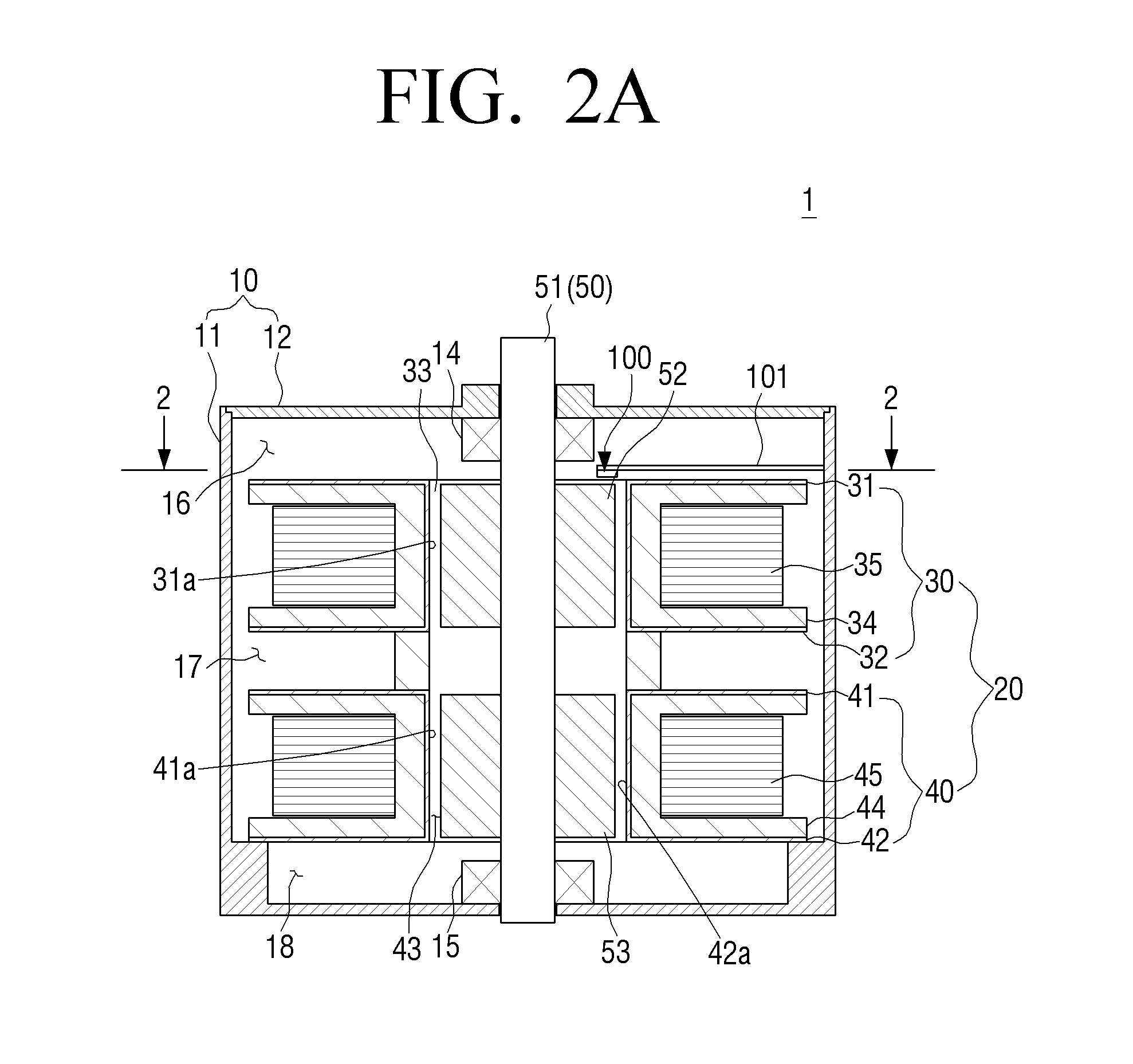
[0041]FIG. 1 is an exploded perspective view schematically illustrating a stepping motor, according to an embodiment of the present disclosure. FIG. 2A is a cross-sectional view schematically illustrating a stepping motor, according to an embodiment of the present disclosure, FIG. 2B is a cross-sectional vi...


PUM


Abstract

A stepping motor includes a housing, a stator assembly, a rotor, and a sensor portion. The stator assembly is disposed inside the housing. The rotor is rotatably disposed inside the stator assembly and includes a rotation shaft, and opposite ends of the rotation shaft are supported by the housing. The sensor portion is disposed inside the housing and detects a magnetic field of the rotor.

Description

CROSS-REFERENCE TO RELATED APPLICATIONS[0001]This application claims the priority benefit under 35 U.S.C. §119(a) from Korean Patent Application No. 10-2013-0112164 filed Sep. 17, 2013 in the Korean Intellectual Property Office, the disclosure of which is incorporated herein by reference in its entirety.BACKGROUND[0002]1. Field[0003]The present disclosure relates to a stepping motor. More particularly, the present disclosure relates to a stepping motor and a stepping motor system that can detect a step-out phenomenon by using a sensor disposed inside a housing.[0004]2. Related Art[0005]Stepping motors have widely been used in various fields due to their simple structures and ease of control.[0006]In the case of a camera, a stepping motor is often used as an auto focus actuator.[0007]Such stepping motor is generally composed of a rotor that is a permanent magnet attached to a rotation shaft and rotates, and a stator that is an electromagnet fixed to the outside of the rotor. When a p...

Claims


Application Information

Patent Timeline
Patent Type & Authority Applications(United States)
IPC IPC(8): H02K37/00H02P8/38
CPCH02P8/38H02K37/00H02K37/14H02K11/215H02K11/00
Inventor LEE, KUN-WOOSHIM, JAE-KYUCHO, WOO-JONGKOO, BON-MIN
Owner SAMSUNG ELECTRONICS CO LTD
Why Eureka
Try Eureka