Microfluidic separation device and method of making same

a technology of microfluidic separation and separation column, which is applied in the field of separation column, can solve the problem that existing apparatus and techniques only work, and achieve the effect of reducing the number of splicing and splicing steps

Active Publication Date: 2008-08-14
CALIFORNIA INST OF TECH
View PDF18 Cites 13 Cited by
  • Summary
  • Abstract
  • Description
  • Claims
  • Application Information

AI Technical Summary

Problems solved by technology

Existing apparatus and techniques only work with large quantities of chemicals to be separated and large volumes of liquids functioning as the mobile phase.

Method used


Image

  • Microfluidic separation device and method of making same
  • Microfluidic separation device and method of making same
  • Microfluidic separation device and method of making same

Examples


Embodiment Construction

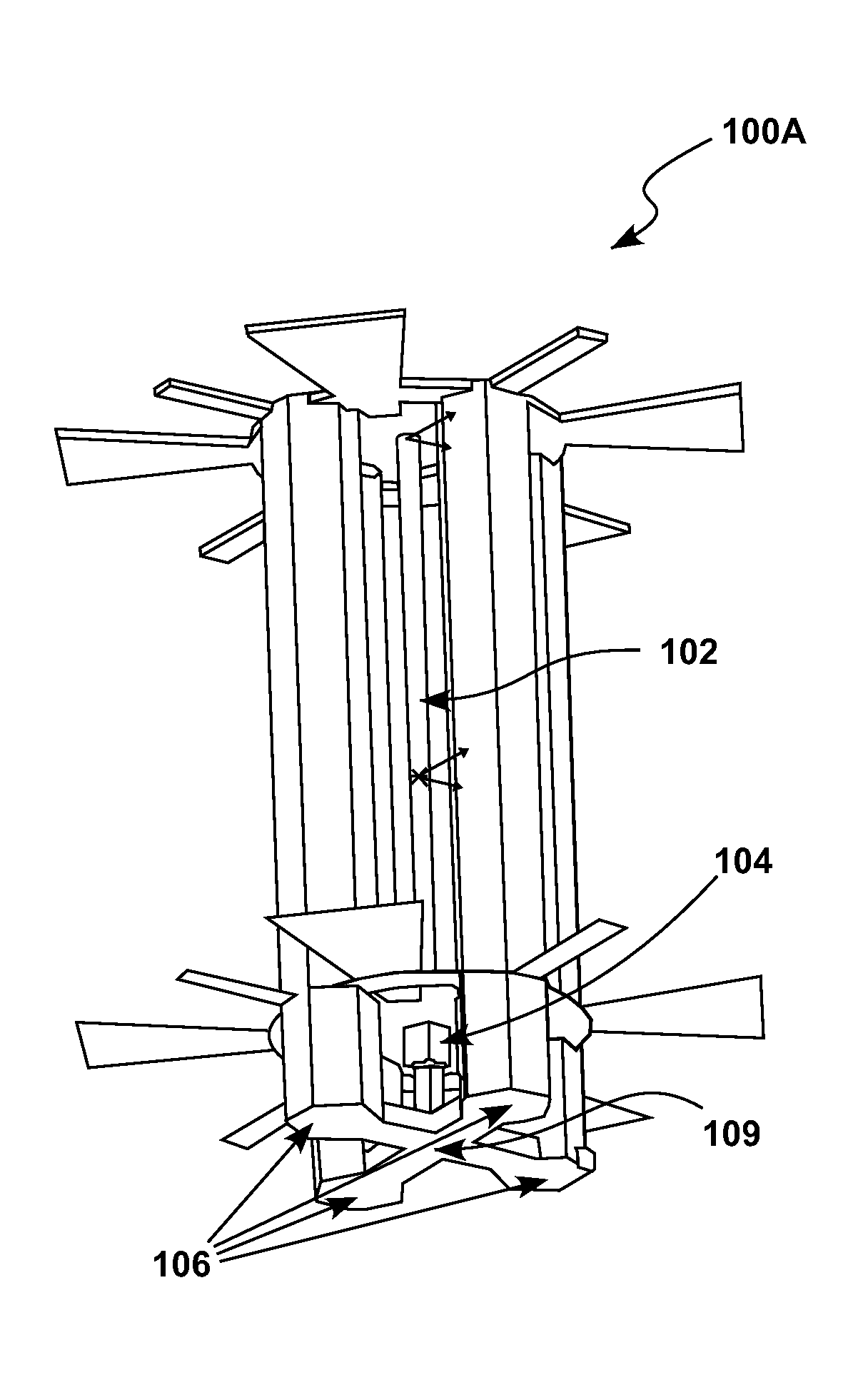
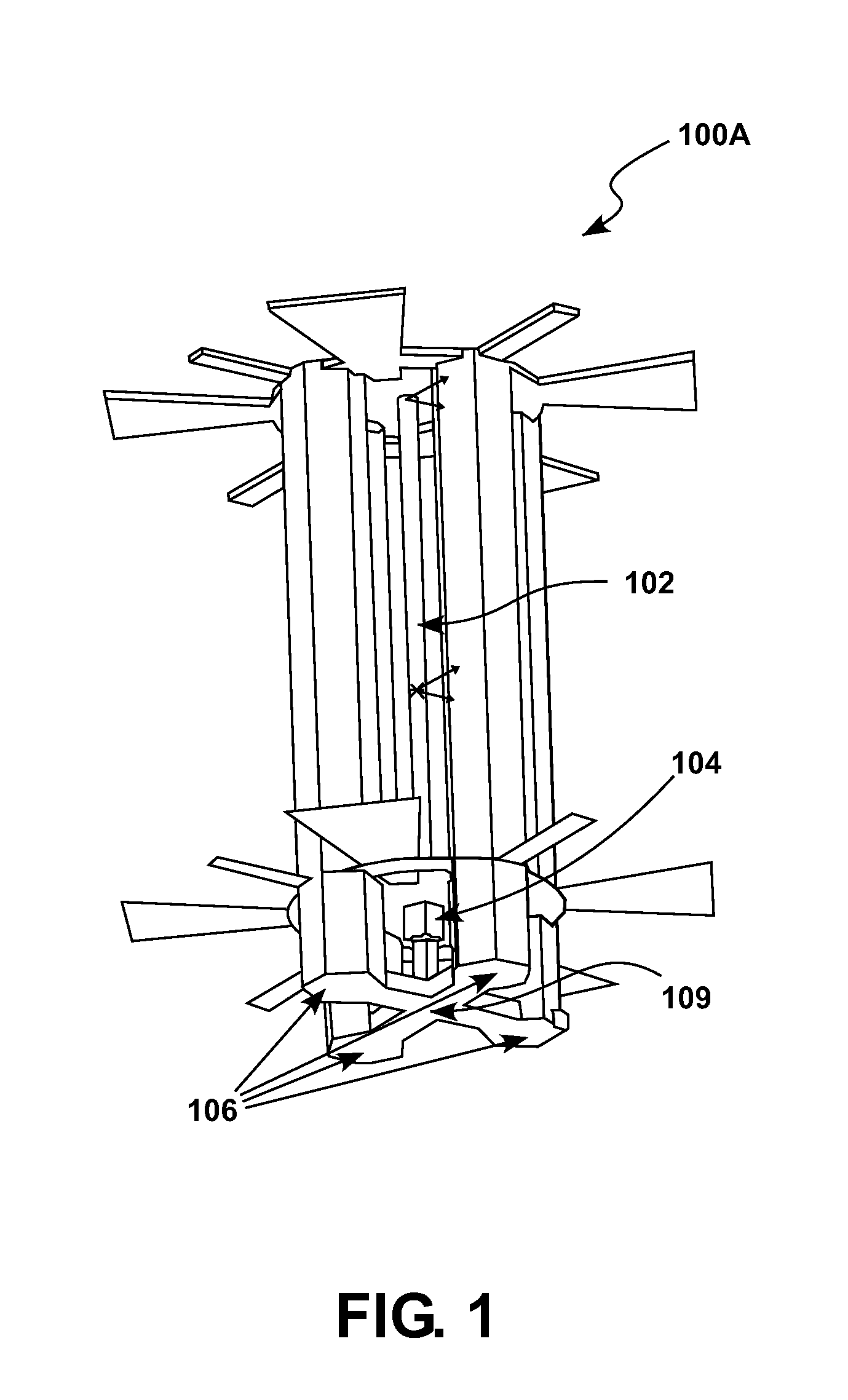
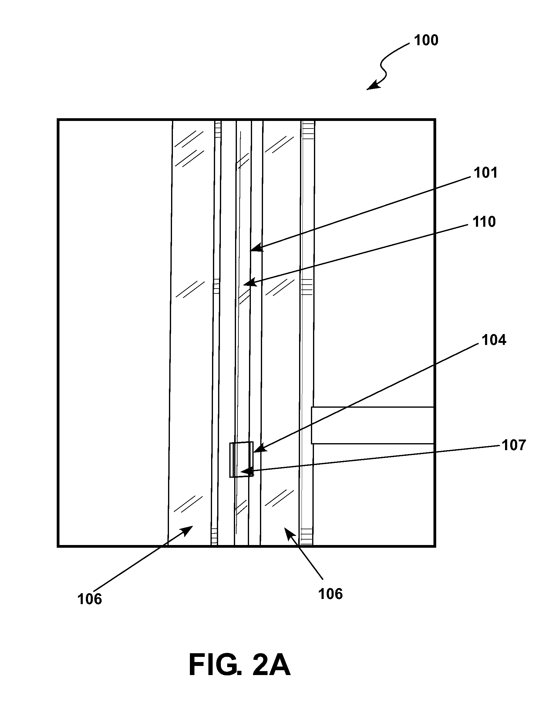
[0028]The present disclosure relates to a device and method for making a microfluidic separation device. In particular, the disclosure pertains to flash chromatography of micro volumes by constructing a microfluidic column capable of separating such micro volumes.

[0029]As disclosed here, a method employing flash chromatography is used. It differs from common gravity chromatography in the sense that it uses pressure to run the molecules through a packed column. In this case, using the three-dimensional “lost wax” approach for microfluidics, a method is presented for miniaturizing a chromatographic column. In the typical “lost wax” approach, a “negative” mold is made. Molten wax is injected into this mold and allowed to cool, thereby generating a wax model. The wax model is covered with plaster of Paris, for example, and heated. The heat melts the wax, which trickles out through a small hole and thus the wax is “lost,” leaving a precise replica of the desired microfluidic separation c...


PUM

PropertyMeasurementUnit
diameteraaaaaaaaaa
diameteraaaaaaaaaa
pressureaaaaaaaaaa

Abstract

A device and method for making a microfluidic separation device. A microfluidic separation device could include a microfluidic column having an inlet, the microfluidic column being configured to hold a first fluid and the microfluidic column including a porous portion, and an outlet attached to the microfluidic column, the outlet being configured to output a second fluid. The method may include providing a microfluidic column having an inlet, configuring the microfluidic column to hold a first fluid, forming a porous portion in the microfluidic column, and attaching an outlet to the microfluidic column.

Description

CROSS-REFERENCE TO RELATED APPLICATIONS[0001]This application claims priority to U.S. Provisional Application No. 60 / 900,425; filed Feb. 9, 2007, titled “Microfluidic Three-Dimensional Separation Column.”STATEMENT REGARDING FEDERALLY SPONSORED RESEARCH OR DEVELOPMENT[0002]This invention was funded by the government under contract numbers DMR-0351848 and DMR-0520565 from the Division of Materials Research, National Science Foundation (NSF), 4201 Wilson Boulevard, Arlington, Va. 22230, USA. The government has certain rights in this invention.INCORPORATION BY REFERENCE[0003]References cited within this application, including patents, published patent applications other publications, such as listed below:U.S. Provisional Application No. 60 / 900,425; filed Feb. 9, 2007, are hereby incorporated by reference in their entirety.THE NAMES OF THE PARTIES TO A JOINT RESEARCH AGREEMENT[0004]California Institute of Technology, Pasadena, Calif., and California State University, Los Angeles, Calif.,...

Claims


Application Information

Patent Timeline
Patent Type & Authority Applications(United States)
IPC IPC(8): B01D15/08
CPCG01N30/6095G01N30/603B01D15/22B01L3/502707B01L3/502753B01L2300/12B01L2300/16B29C65/70B29K2027/12B29L2031/756Y10T29/49826
Inventor MALTEZOS, GEORGEGOMEZ, ALVAROGOMEZ, FRANKSCHERER, AXEL
Owner CALIFORNIA INST OF TECH
Why Eureka
Try Eureka