Mooring Strap

Inactive Publication Date: 2008-08-21
FERNUNG RICK E
View PDF12 Cites 27 Cited by
  • Summary
  • Abstract
  • Description
  • Claims
  • Application Information

AI Technical Summary

Benefits of technology

[0008]The present invention relates to a mooring strap for a vessel having loops at the opposed ends for engaging respective cleats. A lock mechanism interconnects the strap extending from each loop to permit adjust

Problems solved by technology

This procedure is time-consuming and may be enhanced by having two seamen working together to secure an ap

Method used


Image

  • Mooring Strap
  • Mooring Strap

Examples


Example

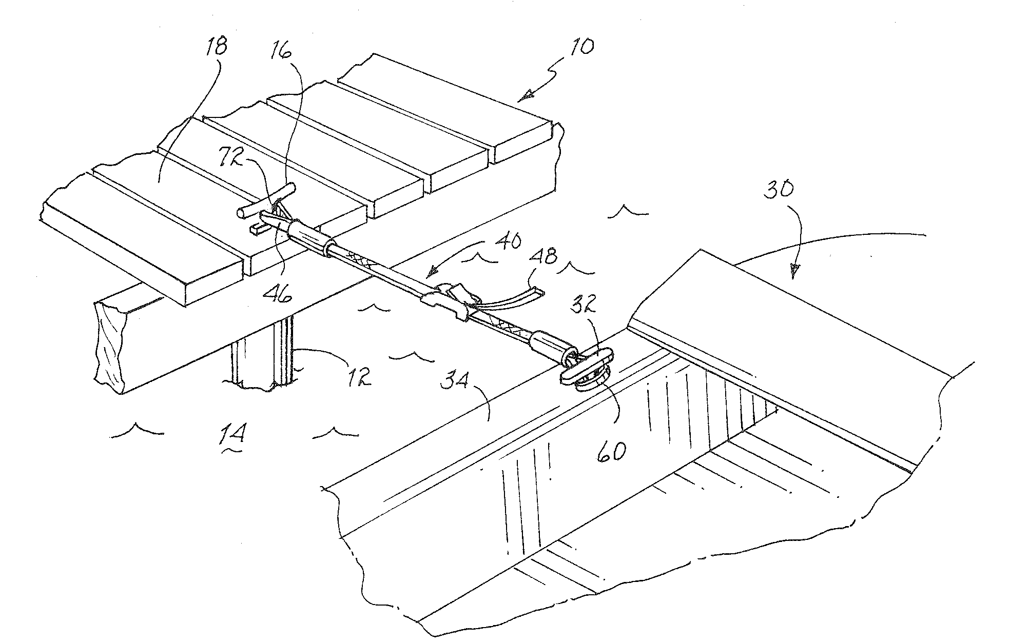
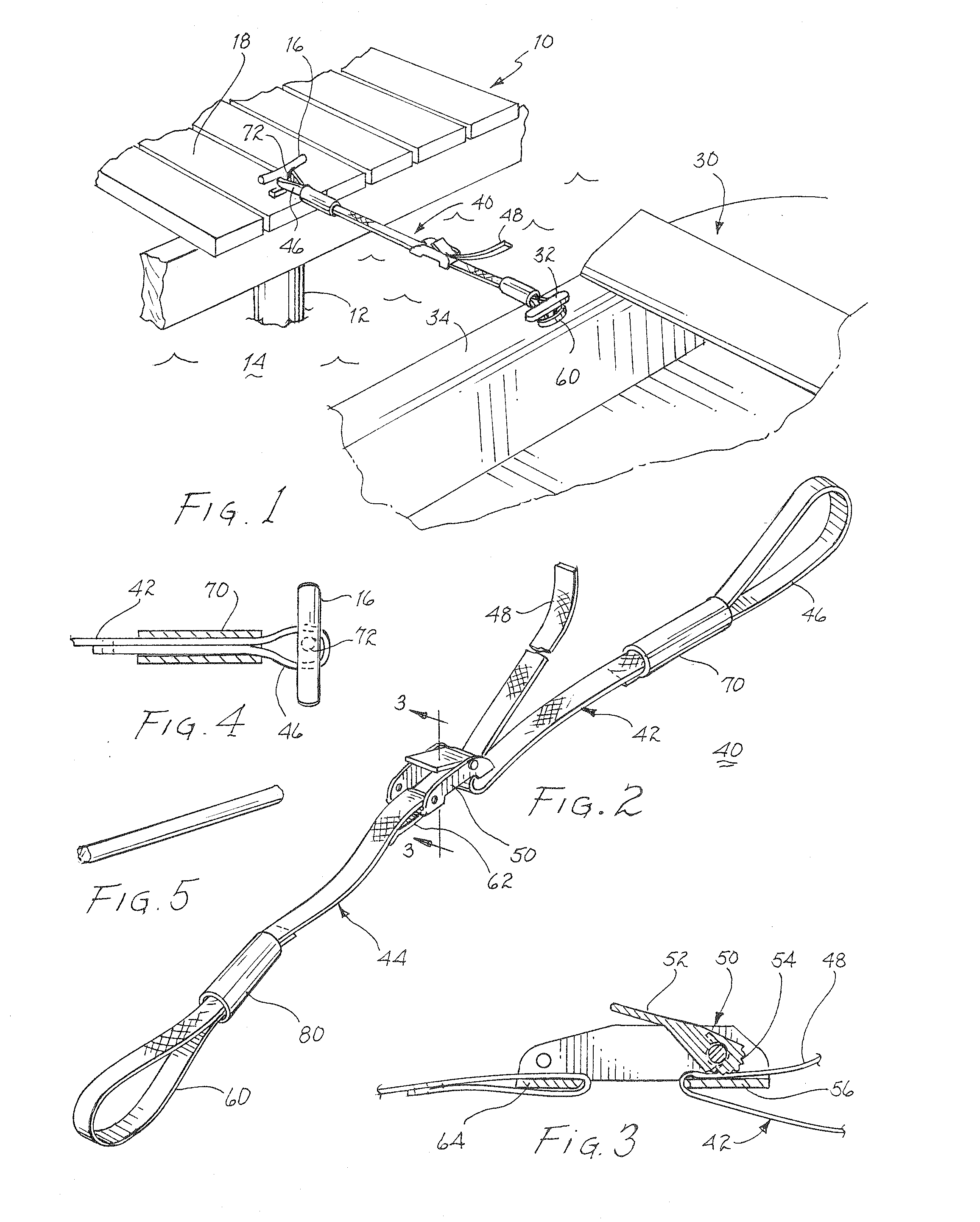
[0023]Referring to FIG. 1, there is illustrated a representative dock 10 supported upon posts 12 anchored in the bottom below water 14. A conventional cleat 16 is attached to dock 10. The cleat may be attached to a board 18 of the dock or other robust member of the dock to serve an anchoring function for a moored vessel.

[0024]A water borne vessel 30, which may be a motorboat, sailboat, rowboat, etc. usually includes a number of cleats mounted on the deck of the vessel or upon the gunwhale. As shown in FIG. 1, cleat 32 is mounted upon gunwhale 34. These cleats may be used for any of a number of purposes, depending upon the type of vessel involved. Usually, one or more cleats are mounted on the deck or the gunwhale of the vessel to permit mooring of the vessel to a dock, other vessel, buoy or post extending from the water. Sometimes these cleats are also used to secure the line for an anchor.

[0025]As illustrated in FIG. 1, a mooring strap 40 is used to moor vessel 30 to dock 10. The m...


PUM


Abstract

A mooring strap for vessels includes a first loop for engaging a dock mounted cleat and a second loop for engaging a cleat on a vessel. A strap extending from each of the two loops is interconnected with a cam lock to permit drawing the two loops toward one another to draw the vessel toward the dock and to secure the vessel with the dock. A sleeve attendant each loop is slid toward a loop engaged cleat to reduce the functional size of the loop and thereby prevent the loop from becoming inadvertently disengaged from the cleat. Upon release of the cam lock and drawing the sleeves away from the respective engaged cleats, the mooring strap may be disengaged from the cleats.

Description

BACKGROUND OF THE INVENTION[0001]1. Field of the Invention[0002]The present invention relates to mooring lines for vessels and, more particularly, to a mooring strap having loops at the ends with a lock mechanism to adjust the distance between the loops.[0003]2. Description of Related Art[0004]Since time immemorial, water borne vessels have been moored to docks with lines engaging a cleat, or the like, on the vessel and a cleat attached to the dock or a post formed as part of the dock. When two vessels are moored adjacent one another, lines are used to engage a cleat of one vessel with a cleat of another vessel. Usually, fenders are deployed intermediate the vessel and the dock or between two vessels to prevent abrading or damage causing contact therebetween.[0005]Sometimes a vessel is moored between two pairs of posts. Again, lines are used to engage each post and a cleat or other fixed elements on the vessel.[0006]All of these pre-existing procedures for mooring a vessel usually r...

Claims


Application Information

Patent Timeline
IPC IPC(8): B63B21/00
CPCB63B21/08B63B21/00
Inventor FERNUNG, RICK E.
Owner FERNUNG RICK E
Why Eureka
Try Eureka