Signal transmission system

a transmission system and signal technology, applied in the field of signal transmission systems, can solve the problems of requiring a lot of hardware and drawbacks

Inactive Publication Date: 2008-08-28
NISHIO TOSHIRO +1
View PDF36 Cites 18 Cited by
  • Summary
  • Abstract
  • Description
  • Claims
  • Application Information

AI Technical Summary

Benefits of technology

[0011]Therefore, it is possible to realize a signal transmission system in which hardware configurations at the video signal transmitting end and receiving end can be simplified.
[0035]Therefore, it is possible to realize a signal transmission system which can set parameters for noise removal for every frame.

Problems solved by technology

However, in the above-described conventional signal transmission system, since the transmission path encoding is performed on the RGB signals, the output from the MPEG decoder is once converted into the RGB signals, encoded, and transmitted through the transmission path and, thereafter, the RGB signals must be converted into the YPBPR to perform signal processing again on the monitor side and, further, the Y color-difference signals must be converted into the RGB signals once again to output the RGB signals to the final display device, resulting in a drawback of requiring a lot of hardware.

Method used


Image

  • Signal transmission system
  • Signal transmission system
  • Signal transmission system

Examples


embodiment 1

[0056]Hereinafter, a signal transmission system according to a first embodiment of the present invention will be described with reference to FIG. 1.

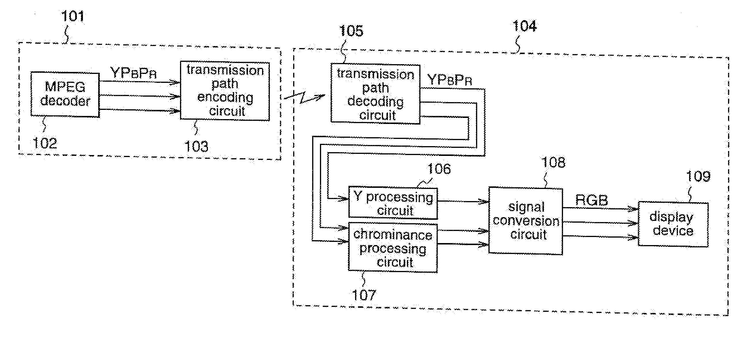
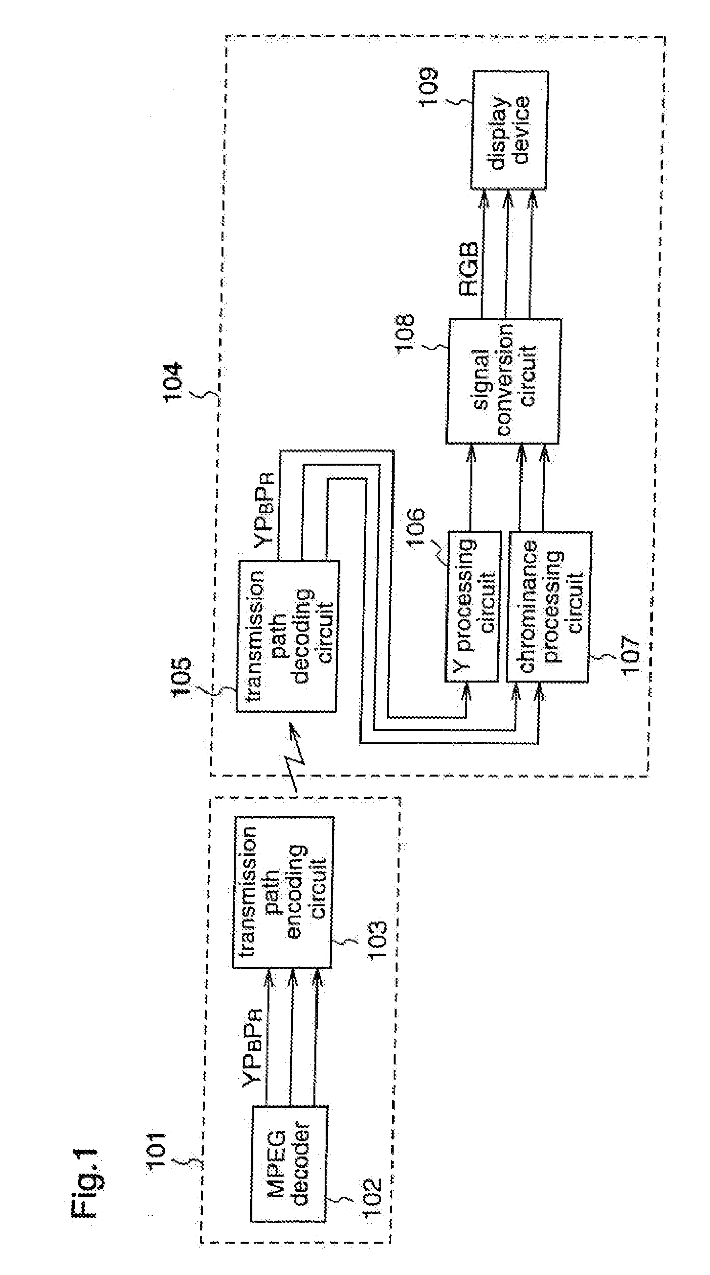
[0057]FIG. 1 is a block diagram illustrating the configuration of the signal transmission system according to the first embodiment of the present invention.

[0058]In FIG. 1, numeral 101 denotes a video signal output unit such as a STB, which outputs a video signal. Numeral 102 denotes an MPEG decoder, which receives digital broadcasting or the like and outputs a luminance signal and two color-difference signals. Numeral 103 denotes a transmission path encoding circuit, which encodes the luminance signal and the color-difference signals outputted from the MPEG decoder 102 into signals in the forms suited to a transmission path, and transmits these signals. Numeral 104 denotes a display unit such as a TV monitor, which displays the video signal. Numeral 105 denotes a transmission path decoding circuit, which receives the luminance signal an...

embodiment 2

[0063]Hereinafter, a signal transmission system according to a second embodiment of the present invention will be described with reference to FIG. 2.

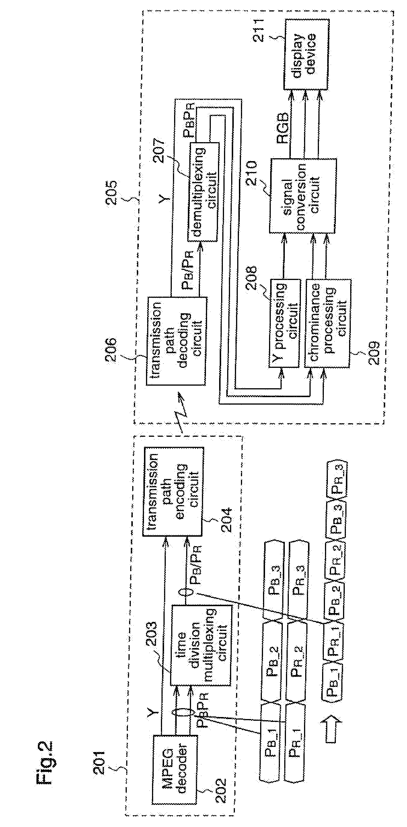
[0064]FIG. 2 is a block diagram illustrating the configuration of the signal transmission system according to the second embodiment of the present invention.

[0065]In FIG. 2, numeral 201 denotes a video signal output unit such as a STB, which outputs a video signal. Numeral 202 denotes an MPEG decoder, which receives digital broadcasting or the like and outputs a luminance signal and two color-difference signals. Numeral 203 denotes a time division multiplexing circuit, which time-division-multiplexes color difference signals PB and PR that have been outputted from the MPEG decoder 202 and converts them into a single signal line. Numeral 204 denotes a transmission path encoding circuit, which encodes the Y signal outputted from the MPEG decoder 202 and the multiplexed PBPR signal outputted from the time division multiplexing circuit 203 ...

embodiment 3

[0070]Hereinafter, a signal transmission system according to a third embodiment of the present invention will be described with reference to FIGS. 3 to 7.

[0071]FIG. 3 is a block diagram schematically illustrating the configuration of the signal transmission system according to the third embodiment of the present invention.

[0072]In FIG. 3, numeral 301 denotes a STB for receiving digital broadcasting or the like, which outputs a video signal. Numeral 302 denotes a TV monitor which displays the video signal received from the STB 301. It is assumed that 12C bidirectional communication is possible between the STB 301 and the TV monitor 302.

[0073]FIG. 4 is a block diagram for explaining the STB 301 and the TV monitor 302 in detail. In FIG. 4, the same or corresponding constituent elements as those shown in FIG. 3 are denoted by the same reference numerals, and their descriptions will be omitted.

[0074]In FIG. 4, numeral 402 denotes an MPEG decoder, which receives digital broadcasting or th...


PUM


Abstract

A signal transmission system according to the present invention, in one embodiment comprises: a signal transmission unit that includes a MPEG decoder which receives digital broadcasting and outputs a luminance signal Y and two color difference signals PB / PR, and a transmission path encoding circuit which encodes the YPBPR outputted from the MPEG decoder into signals in the forms suited to a transmission path and transmits the encoded signals; and a signal reception unit that includes a transmission path decoding circuit which receives the encoded YPBPR and decodes them, a Y processing circuit which processes the decoded luminance signal Y, a chrominance processing circuit which processes the respective decoded color difference signals PB / PR, a signal conversion circuit which converts the YPBPR outputted from the Y processing circuit and the chrominance processing circuit into RGB signals, and a display device which displays the RGB signals. According to the so-configured signal transmission system, it is possible to realize a signal transmission system in which hardware configurations of the video signal transmitting end and receiving end can be simplified.

Description

CROSS REFERENCE TO RELATED APPLICATIONS[0001]This application is a continuation application of U.S. patent application Ser. No. 10 / 088,468, (U.S. Patent Publication No. US2002163970) filed Jun. 11, 2002 entitled, “Signal Transmission System,” incorporated herein by reference, which is a national stage application under 35 U.S.C. §371 of PCT / JP01 / 06340 filed Jul. 23, 2001 entitled, “Signal Transmission System,” incorporated herein by reference, which claims priority to Japanese Patent Application No. 2000-220751 filed Jul. 21, 2000 entitled, “Signal Transmission System.” Priority of each of the above applications is claimed.FIELD OF THE INVENTION[0002]The present invention relates to a signal transmission system for transmitting picture signals and, more particularly, to a signal transmission system in which hardware configurations of the video signal transmitting end and receiving end can be simplified.BACKGROUND OF THE INVENTION[0003]A prior art example will be described with refer...

Claims


Application Information

Patent Timeline
Patent Type & Authority Applications(United States)
IPC IPC(8): H04N11/02H04N7/173H04N9/00H04N11/04H04N21/4363
CPCH04N11/042H04N19/00533H04N19/44H04N11/04H04N9/64
Inventor NISHIO, TOSHIRONIO, YUTAKA
Owner NISHIO TOSHIRO
Why Eureka
Try Eureka