Supercharge Your Innovation With Domain-Expert AI Agents!

Synchromesh automatic transmission

a transmission and automatic technology, applied in the direction of gearing, mechanical control devices, instruments, etc., can solve the problems of difficult to cope with each transmission type, the inability to control the shift fork,

Inactive Publication Date: 2008-09-04
MITSUBISHI MOTORS CORP
View PDF0 Cites 18 Cited by
  • Summary
  • Abstract
  • Description
  • Claims
  • Application Information

AI Technical Summary

Benefits of technology

[0011]An object of the present invention is to provide a synchromesh automatic transmission, which can control a shift fork of a shift stage different from a target shift stage, upon shift of the target shift stage, so as to be located at a neutral position without being influenced by movement of a shift finger of the target shift stage in a shift direction.
[0012]The synchromesh automatic transmission according to the present invention employs a structure to provide an interlock mechanism for controlling a shift fork different from a target shift stage so as to be located at a neutral position by having a lug lock portion that can control the shift fork at a neutral position being engaged with the shift lug other than the shift finger, displacing this lug block part following the movement of the shift finger in the selection direction, and engaging this lug block part with the shift lug of the shift fork of the shift stage different from the target shift stage, in addition to a shift selector mechanism to achieve a target shift stage by engaging the shift finger with the shift lug of the shift fork corresponding to the target shift stage and displacing this shift fork in the shift direction.

Problems solved by technology

Therefore, in the above-described structure, the interlock cam and the interlock plate may be arranged at a position deviated from the shift lug to be engaged due to an error of each part or the like, and according to the circumstances, it is feared that the shift fork cannot be controlled so as to be located at the neutral position.
Therefore, this structure has a problem that, if the movement of the shift lug in the shift direction is changed, for example, for each kind of transmission, a structure to enable movement in the shift direction is required for each transmission and thus it is difficult to cope with each kind of transmission.

Method used


Image

  • Synchromesh automatic transmission
  • Synchromesh automatic transmission
  • Synchromesh automatic transmission

Examples


first embodiment

[0049]Hereinafter, a first embodiment according to the present invention will be described on the basis of FIGS. 1 to 12.

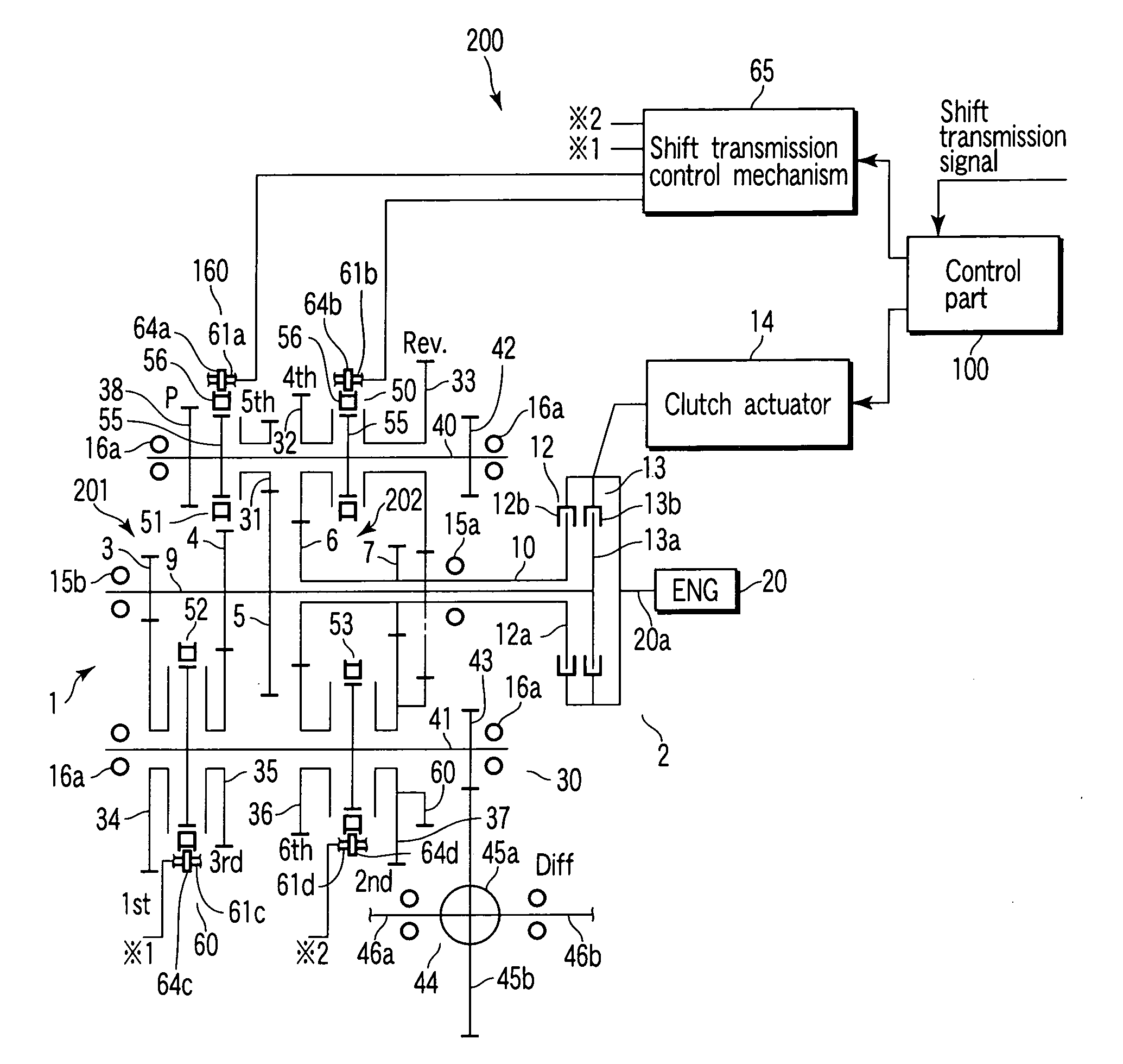
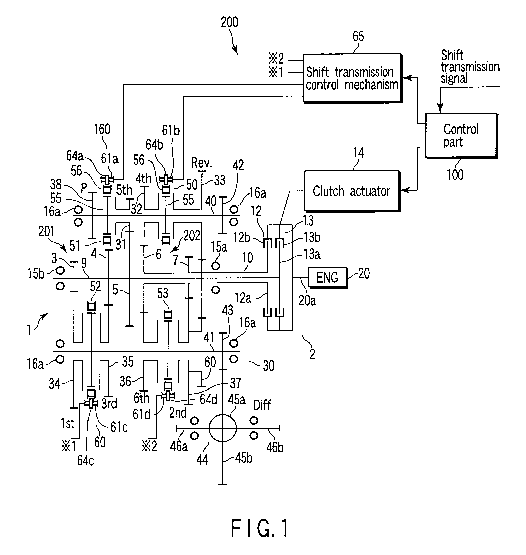
[0050]FIG. 1 shows a schematic structure of an automatic transmission of a vehicle (car), for example, a synchromesh automatic transmission 200 using a twin clutch having a shift stage of a total of seven gear speed shifts, i.e., a front stage having six gear speed shifts and a rear stage having one gear speed shift. In FIG. 1, reference numeral 1 denotes a twin clutch transmission mechanism. The twin clutch transmission mechanism 1 is formed by combining an input system 2 and an output system 30. The input system 2 uses the structure in which two (plural) input shafts 9 and 10 on which plural driving gears 3 to 7 are arranged and two (plural) sets of clutches 12 and 13 are combined. The output system 30 uses the structure having two output shafts 40 and 41, on which driven gears 31 to 37 and synchronous mechanisms 50 to 53 are arranged.

[0051]The input system 2 wi...

third embodiment

[0095]A synchromesh automatic transmission according to this invention will be described with reference to FIG. 14.

[0096]FIG. 14 shows a third embodiment of the present invention.

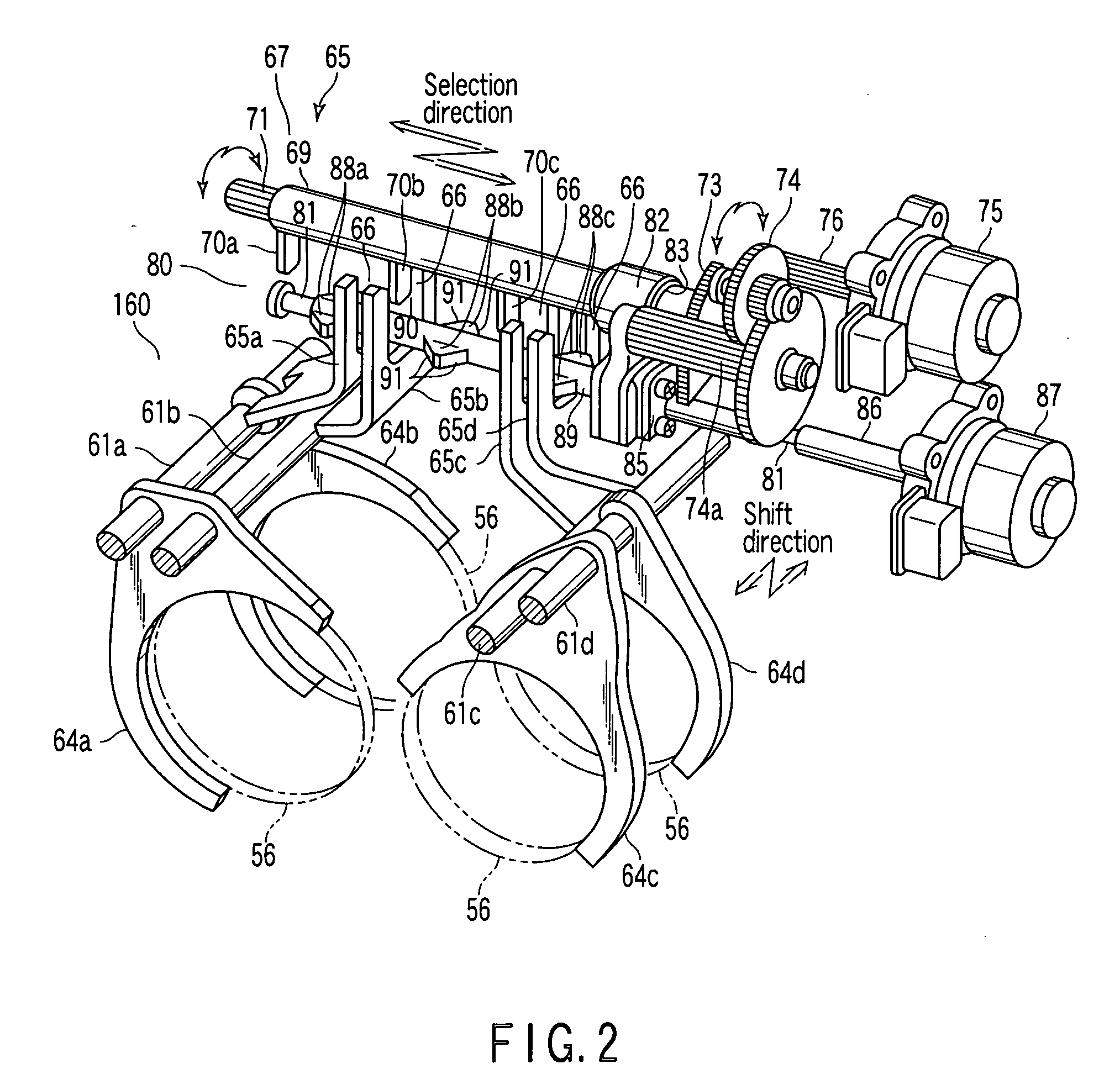
[0097]The present embodiment is a modified example of the interlock mechanism 80. The lug lock portions 88a to 88c in a tubular shape according to the second embodiment are meshed with the ball screw shaft 81 so as to move forward and backward, and these respective lug lock portions 88a to 88c are coupled to the selector shaft 69 by the joint member 82. Then, as in the first embodiment, the lug lock portions 88a to 88c are to be displaced following movement of the shift fingers 70a to 70c in the selection direction.

[0098]In this way, as in the first embodiment, the neutral control of the shift fork different from the target shift stage can be also carried out without being influenced by movement of the shift fingers 70a to 70c in the shift direction.

[0099]This embodiment produces the same advantages as the ...

fifth embodiment

[0104]FIG. 16 shows the present invention.

[0105]The present embodiment is a modified example of the third embodiment. According to the present embodiment, by supporting the shift fingers 70a to 70c so as to be slid in lateral directions by using two slider mechanisms 120 and 121, movement in the shift direction is secured from the slide displacement in the lateral directions.

[0106]This embodiment produces the same advantages as the first and second embodiments.

[0107]Further, in the first to fifth embodiments, examples in which the present invention is applied to the synchromesh automatic transmission having the twin clutch transmission mechanism have been described. However, without being limited to this, the present invention may be also applied to a synchromesh automatic transmission having a transmission mechanism such as a normal synchromesh transmission mechanism, like the one in the sixth embodiment as shown in FIG. 17, namely, for example, a transmission mechanism having the ...


PUM


Abstract

A synchromesh automatic transmission includes a lug lock portion which is engaged with a shift lug separately from a shift finger and enables a shift fork to be controlled so as to be located at a neutral position, a shift selector mechanism which achieves a target shift stage by engaging the shift finger with the shift lug of the shift fork corresponding to the target shift stage and displacing this shift fork in a shift direction, and an interlock mechanism which controls a shift fork that is different from the target shift stage so as to be located at a neutral position by displacing the lug lock portion following movement of the shift finger in a selection direction and engaging this lug lock portion with the shift lug of the shift fork that is different from the target shift stage.

Description

CROSS-REFERENCE TO RELATED APPLICATIONS[0001]This application is based upon and claims the benefit of priority from prior Japanese Patent Application No. 2007-051761, filed Mar. 1, 2007, the entire contents of which are incorporated herein by reference.BACKGROUND OF THE INVENTION[0002]1. Field of the Invention[0003]The present invention relates to a synchromesh automatic transmission for selecting a shift lug of a target shift stage from a plurality of shift lugs aligned in a row and displacing the shift lug in a shift direction by a shift finger.[0004]2. Description of the Related Art[0005]An automatic transmission of a vehicle (car) has a structure to carry out transmission of a target shift stage by using a synchromesh.[0006]In such a synchromesh automatic transmission, a structure is used in which a shift lug is provided to a plurality of shift forks for carrying out gear change of various shift stages, respectively, and by using a shift finger, only one shift lug corresponding ...

Claims


Application Information

Patent Timeline
IPC IPC(8): F16H61/00
CPCF16H3/006F16H61/32F16H61/688F16H63/20F16H63/3408F16H63/36Y10T74/19251F16H2200/0052F16H2063/025F16H2063/208Y10T74/19233Y10T74/20098Y10T74/20104F16H2003/0931F16H63/32
Inventor MURAKAMI, TSUYOSHIYAMAURA, HIROKIKOMORI, KATSUHIROMATSUMOTO, KOJI
Owner MITSUBISHI MOTORS CORP
Features
  • R&D
  • Intellectual Property
  • Life Sciences
  • Materials
  • Tech Scout
  • Unparalleled Data Quality
  • Higher Quality Content
  • 60% Fewer Hallucinations
Learn More