
Diffusion sheet, rear projection screen provided with diffusion sheet, method of manufacturing mold for diffusion sheet, and method of manufacturing diffusion sheet

a technology of diffusion sheet and rear projection screen, which is applied in the direction of projectors, instruments, optics, etc., can solve the problems of lens surface scratching and dirty, lens cannot be joined to the unit lens portion to support, and the surface of the lens cannot be wiped by hand

Inactive Publication Date: 2008-09-04
DAI NIPPON PRINTING CO LTD
View PDF11 Cites 8 Cited by
  • Summary
  • Abstract
  • Description
  • Claims
  • Application Information

AI Technical Summary

Benefits of technology

The diffusion sheet provides excellent bright uniformity and reduced variability in brightness when viewed from different angles, enhancing the overall image quality and simplifying the manufacturing process of the mold for the diffusion sheet.

Problems solved by technology

However, since each unit lens portion of the first and second lenticular lens sheets described above has the curved surface formed on the light outgoing side vertex, a problem arises in that a support sheet cannot be joined to the unit lens portions to support them.
Further, a problem also arises in that a lens is liable to be scratched and made dirty because a light outgoing surface of the lenticular lens sheet is formed in an irregular shape due to the curved surfaces of the unit lens portions, and thus the surface thereof cannot be wiped by hand.
Further, since a light absorbing portion cannot be formed to absorb and shield external light in the second lenticular lens sheet described above, the second lenticular lens sheet is disadvantageous in that when an observer views a display, it is difficult for an observer to observe an image because a contrast is low in a bright portion and a dark portion.
Further, the second lenticular lens sheet is also disadvantageous in that it is difficult to enhance the resolution of an image by miniaturizing a lenticular lens because the second lenticular lens sheet is formed in a complex shape.
When, for example, the observation angles at both the right and left ends of the rear projection type television are approximately in agreement with an angle showing a minimum value of the gain curve, the difference between the brightness in the central portion of the television and the brightness at both the ends thereof extremely increases, thereby the observer views an image having extremely bad bright uniformity.
At the time, a problem arises in that an image having good bright uniformity cannot be viewed because the bad bright uniformity described above is also added.
However, there is also a case that a metal mold is manufactured so as to have such as a shape that projections formed to a metal material are deformed (elastically deformed) inward when viewed from recesses being processed, and projections formed between adjacent recesses tilt from the sides of recesses formed previously toward the sides of recesses formed subsequently, adversely to the above case.
Accordingly, when the observer views the image while moving in a horizontal direction from one end side to the other end side of the rear projection type television using the lenticular lens sheet 701 (while moving from the right side to the left side of FIG. 19B), the image is viewed in the sequence of “dark, bright, dark, bright, dark, bright” at the center of a screen, from which a problem arises in that it is difficult to view the image because irregular brightness is caused in the image.
Further, when the observer views the image displayed on the rear projection type television using the lenticular lens sheet 701 from the front, a problem arises in that he or she views the image having a bad right / left balance, that is, bad bright uniformity.

Method used


Image

  • Diffusion sheet, rear projection screen provided with diffusion sheet, method of manufacturing mold for diffusion sheet, and method of manufacturing diffusion sheet
  • Diffusion sheet, rear projection screen provided with diffusion sheet, method of manufacturing mold for diffusion sheet, and method of manufacturing diffusion sheet
  • Diffusion sheet, rear projection screen provided with diffusion sheet, method of manufacturing mold for diffusion sheet, and method of manufacturing diffusion sheet

Examples


example 1-1

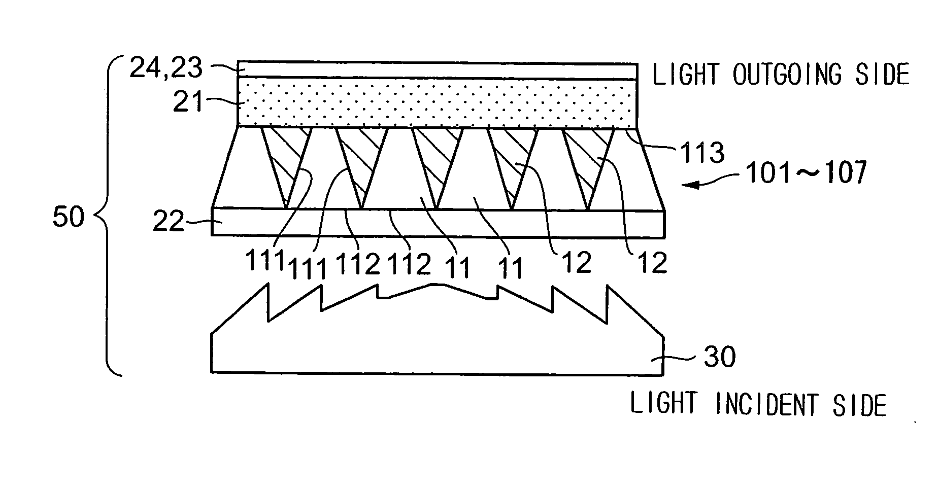
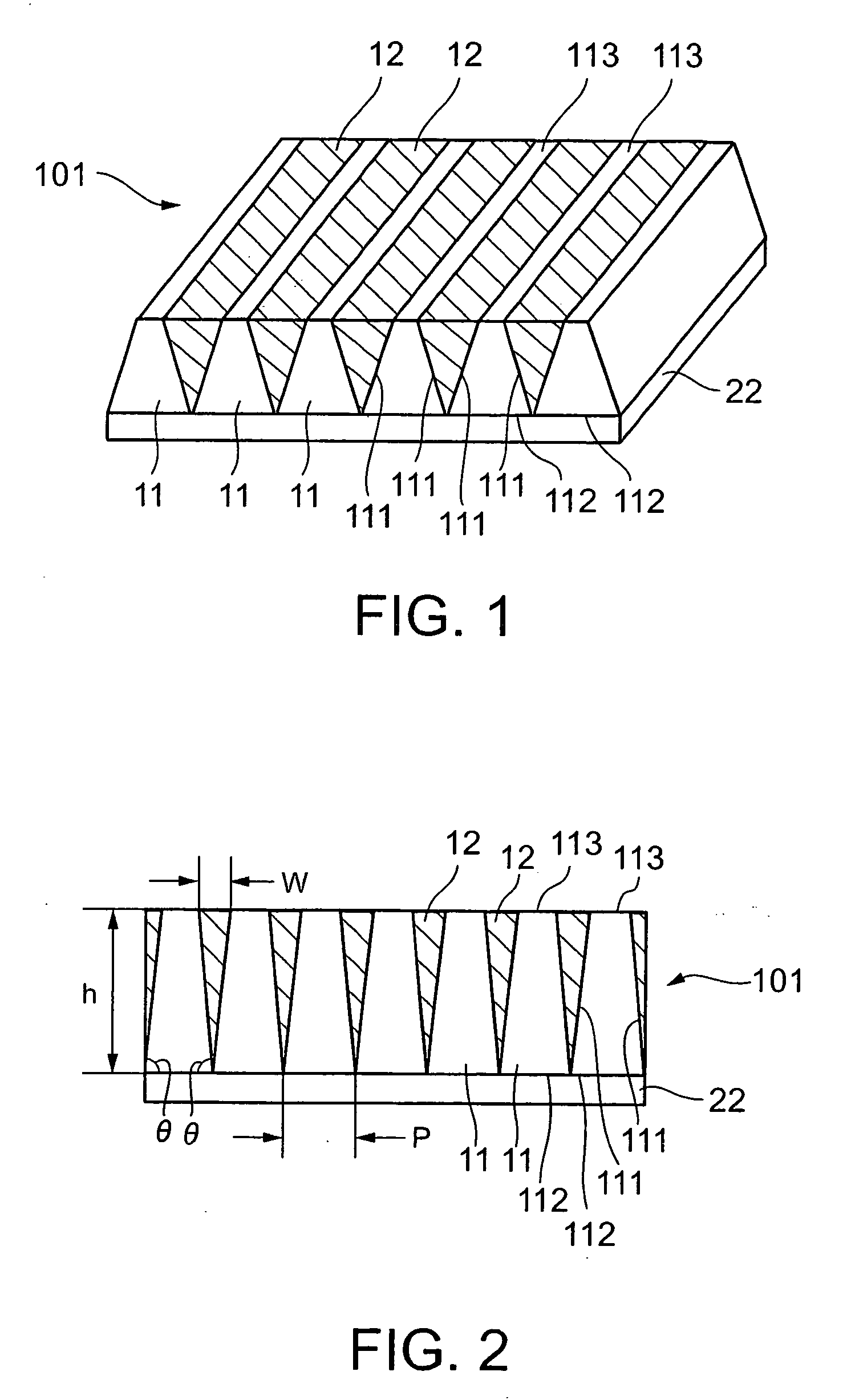
[0188]A diffusion sheet as shown in FIGS. 1 and 2 was manufactured as a diffusion sheet according to an example 1-1.

[0189]Specifically, first, a roll-shaped metal mold was prepared by sequentially cutting a metal mold material to form recesses for unit lens portions so that a diffusion sheet, in which a plurality of unit lens portions were continuously disposed, was molded by the metal mold. The plurality of unit lens portions molded by the metal mold were such that the horizontal section of each of the unit lens portions was formed in an isosceles trapezoidal shape, the pitch p of the unit lens portions was set to 70 μm, a lens height h was set to 140 μm, the ratio of the length w of the light outgoing side bottom segment of the triangular section of each light absorbing portion to the pitch p (w / p) was set to 56%, and the angle θ between a light incident surface and a side surface (total reflection surface) was set to 82°.

[0190]A UV resin was buried in the roll-shaped metal mold p...

example 1-2

[0193]A diffusion sheet as shown in FIG. 4A was manufactured as a diffusion sheet according to an example 1-2.

[0194]Specifically, the diffusion sheet was formed in the shape shown in Table 1 as a whole by alternately disposing two types of isosceles trapezoidal columnar unit lens portions, that is, one type of the isosceles trapezoidal columnar unit lens portion had an angle θ1 of 80° between a light incident surface and each side surface (total reflection surface), and the other type of the isosceles trapezoidal columnar unit lens portion had an angle θ2 of 82° between a light incident surface and each side surface (total reflection surface). The diffusion sheet as shown in FIG. 4A was manufactured likewise the example 1-1 except the above arrangement. Further, a rear projection screen provided with the diffusion sheet described above was obtained likewise the example 1-1.

example 1-3

[0195]A diffusion sheet as shown in FIG. 5 was manufactured as a diffusion sheet according to an example 1-3.

[0196]Specifically, non-isosceles trapezoidal columnar unit lens portions, in each of which the angle θ3 between one side surface (total reflection surface) and a light incident surface was set to 80° and the angle θ4 between the other side surface (total reflection surface) and the light incident surface was set to 82°, were disposed in such a manner that the surfaces, which correspond to the side segments having the angle θ3, of adjacent unit lens portions were disposed adjacent to each other, and the surfaces, which correspond to the side segments having the angle θ4, of adjacent unit lens portions were disposed adjacent to each other, thereby the diffusion sheet was formed in the shape shown in Table 1. The diffusion sheet as shown in FIG. 5 was manufactured likewise the example 1-1 except the above arrangement. Further, a rear projection screen provided with the diffusio...


PUM


Abstract

In a diffusion sheet 101, a plurality of approximately trapezoidal columnar unit lens portions 11 are disposed such that the long-axis directions thereof are in parallel with each other, and all the surfaces of the unit lens portions, which correspond to the long bottom segments 112 of the approximately trapezoidal sections of the unit lens portions 11 are disposed on a light-incident-side flat surface. Further, light absorbing portions 12 are disposed in the grooves between adjacent unit lens portions 11 to absorb and / or shield external light incident from a light outgoing side. In the diffusion sheet 101 arranged as described above, light incident on the unit lens portions 11 from a light incident side is totally reflected on the surfaces corresponding to the side segments 111 of the approximately trapezoidal sections vertical to the long-axis direction of the unit lens portions and outgoes from the light outgoing side. In each of the unit lens portions 11 arranged as described above, the distance h between both the bottom segments 112 and 113 of the approximately trapezoidal section is 120% or more to 400% or less of the length p of the long bottom segment 112 (h / p=1.20 to 4.00).

Description

[0001]This is a Continuation of application Ser. No. 10 / 518,305 filed Dec. 17, 2004, which is a National Phase of Application No. PCT / JP2004 / 004202 filed Mar. 25, 2004, which claims the benefit of Japanese Patent Application No. 2003-82693 filed Mar. 25, 2003 and Japanese Patent Application No. 2003-119588 filed Apr. 24, 2003. The disclosures of the prior applications are hereby incorporated by reference herein in their entirety.TECHNICAL FIELD[0002]The present invention relates to a diffusion sheet assembled in a rear projection screen (transmission type screen) and used therein, and more particularly, to a diffusion sheet in which a plurality of approximately trapezoidal columnar unit lens portions (unit optical elements) are disposed, a rear projection screen provided with the diffusion sheet, a method of manufacturing a mold for a diffusion sheet, and a method of manufacturing a diffusion sheet.BACKGROUND ART[0003]Heretofore, there is known an image display apparatus having a li...

Claims


Application Information

Patent Timeline
Patent Type & Authority Applications(United States)
IPC IPC(8): G03B21/60G02B5/02G02B5/04
CPCG02B5/021G02B5/0242G02B5/045G02B5/0278G02B5/0268G02B3/08G02B5/003
Inventor KATSURA, YUKIGOTO, MASAHIRO
Owner DAI NIPPON PRINTING CO LTD
Learn More