

Apparatus and method for comfortably and dynamically adjusting the girth of a garment fastened by hook and eye
- Summary
- Abstract
- Description
- Claims
- Application Information
AI Technical Summary
Benefits of technology
Problems solved by technology
Method used
Image

Examples
first embodiment
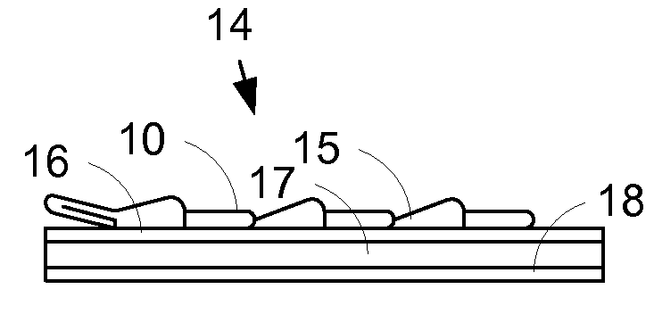
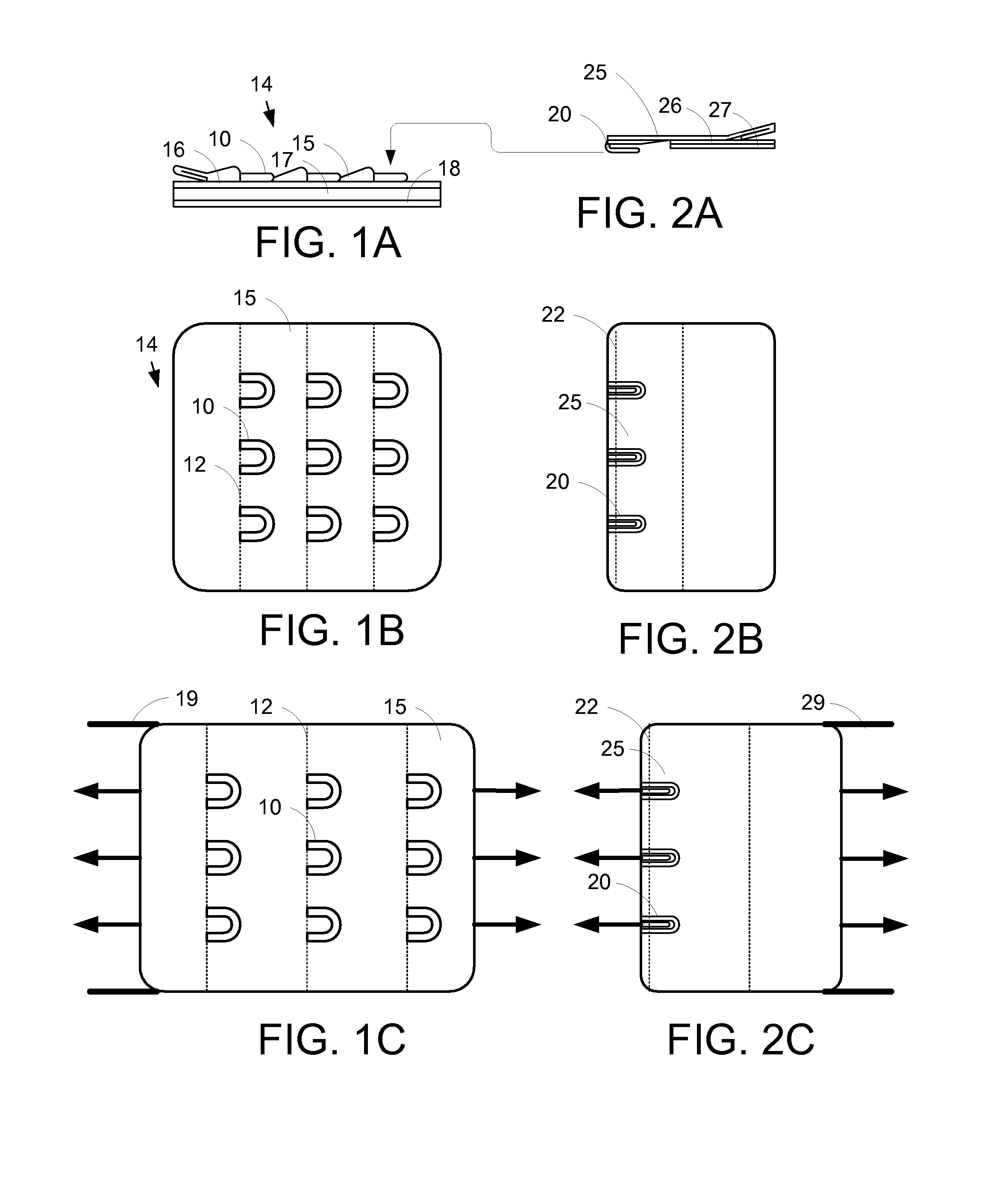
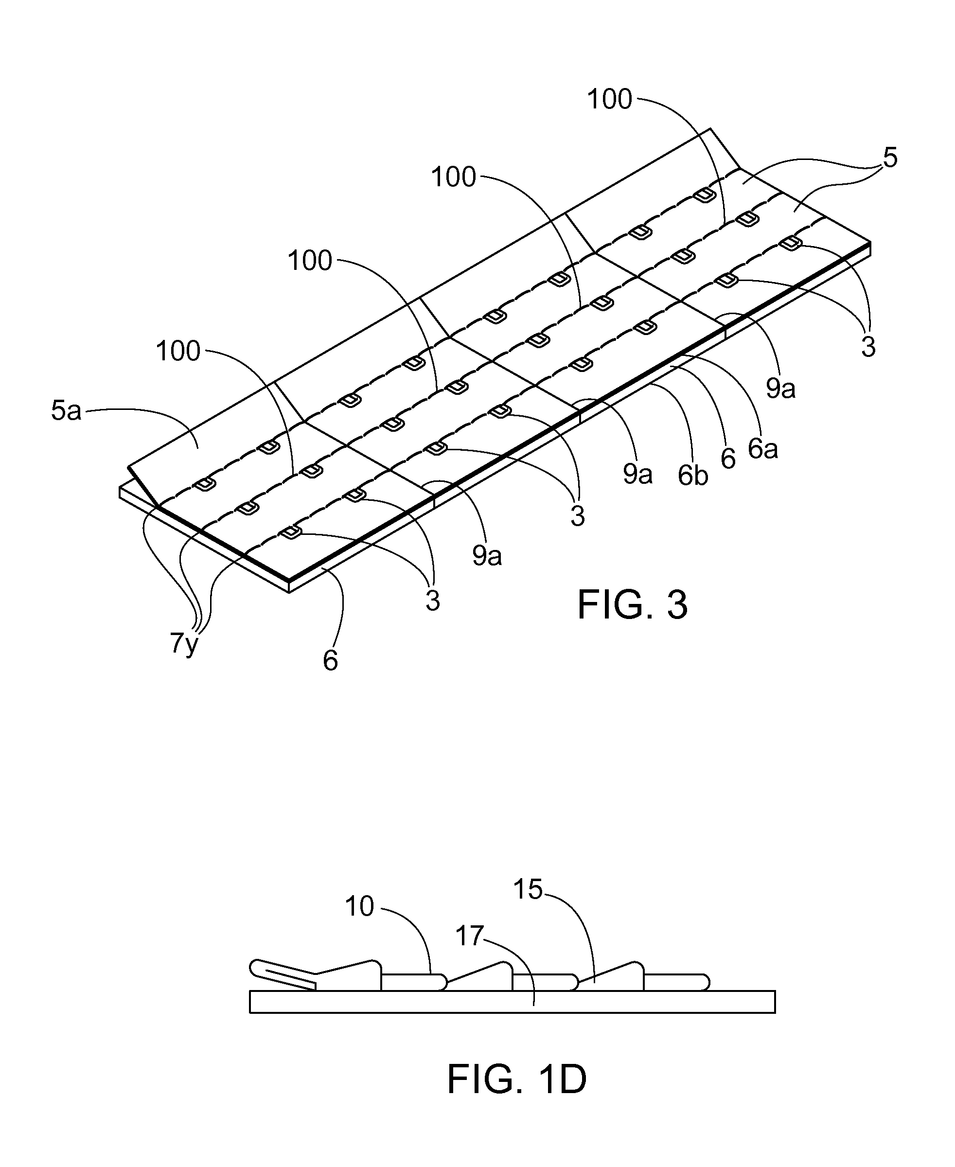
[0049]A first embodiment is drawn to a base tape for a hook and eye closure to allow dynamic girth adjustment of a garment, comprising: a first elastically elongatable fabric layer; at least one additional elastically elongatable layer laminated with adhesive to the first elastically elongatable fabric layer to form an elastically elongatable base tape; and hook or eye closure hardware sewn to the elastically elongatable base tape. This embodiment is not limited to these elements and can include additional structure.
[0050]Variations on this first embodiment include: those wherein the at least one additional elastically elongatable layer comprises a second elastically elongatable layer consisting of cushioning material and a third elastically elongatable layer consisting of fabric that is laminated to the second elastically elongatable layer, wherein the cushioning material can be selected from the group consisting of fabric, stretchable foam, flex foam, and rubber; those wherein the...
second embodiment
[0051]A second embodiment is drawn to a hook and eye closure for allowing dynamic girth adjustment of a garment, comprising: an eye tape, said eye tape comprising: an elastically elongatable base fabric that elongates elastically in a first direction; at least one additional elastically elongatable layer laminated to the base fabric to form a laminated base tape; at least one eye column positioned on said laminated base tape wherein said at least one eye column extends in a second direction perpendicular to the first direction; and at least one eye row in said at least one eye column, each row containing an eye secured to said laminated base tape; a hook tape, said hook tape comprising: a hook base tape; one hook column positioned on said hook base tape in said second direction; and at least one hook row in said at least one hook column, each row containing a hook secured to said hook base tape.
[0052]Variations on this embodiment include: those further comprising: a plurality of par...
PUM
 Abstract
Description
Claims
Application Information