Methods of Forming Integrated Circuit Structures Using Insulator Deposition and Insulator Gap Filling Techniques

a technology of insulator gap filling and integrated circuit structure, which is applied in the direction of coating, chemical vapor deposition coating, semiconductor devices, etc., can solve the problems of reducing device yield and device reliability, forming voids in the spaces between the integrated circuit structure, and reducing the yield of devices

Active Publication Date: 2008-09-11
SAMSUNG ELECTRONICS CO LTD +2
View PDF20 Cites 53 Cited by
  • Summary
  • Abstract
  • Description
  • Claims
  • Application Information

AI Technical Summary

Benefits of technology

[0005]Additional embodiments of the present invention include methods of forming field effect transistors by forming first and second insulated gate electrodes at side-by-side locations on an integrated circuit substrate and then forming a silicon nitride layer on the first and second insulated gate electrodes and in a gap between the first and second insulated gate electrodes. This step of forming the silicon nitride layer may includ

Problems solved by technology

Conventional techniques to increase the levels of device integration on integrated circuit substrates can often lead to reductions in device yield and device reliability.
Some of these reductions in device yield may be caused by the formation of voids or gaps within electrically insulating layers and also within electrical interconnects that may extend through one or more electrically insulating layers.
In particular, the conformal deposition of relatively thick electrically insulating layers on closely-spaced integrated circuit structures having relatively narrow aspect ratios may lead to the formation of voids in the spaces between t

Method used


Image

  • Methods of Forming Integrated Circuit Structures Using Insulator Deposition and Insulator Gap Filling Techniques
  • Methods of Forming Integrated Circuit Structures Using Insulator Deposition and Insulator Gap Filling Techniques
  • Methods of Forming Integrated Circuit Structures Using Insulator Deposition and Insulator Gap Filling Techniques

Examples


Embodiment Construction

[0011]The present invention will now be described more fully hereinafter with reference to the accompanying drawings, in which preferred embodiments of the invention are shown. This invention may, however, be embodied in different forms and should not be construed as limited to the embodiments set forth herein. Rather, these embodiments are provided so that this disclosure will be thorough and complete, and will fully convey the scope of the invention to those skilled in the art. In the drawings, the thickness of layers and regions are exaggerated for clarity. It will also be understood that when a layer is referred to as being “on” another layer or substrate, it can be directly on the other layer or substrate, or intervening layers may also be present. Like numbers refer to like elements throughout.

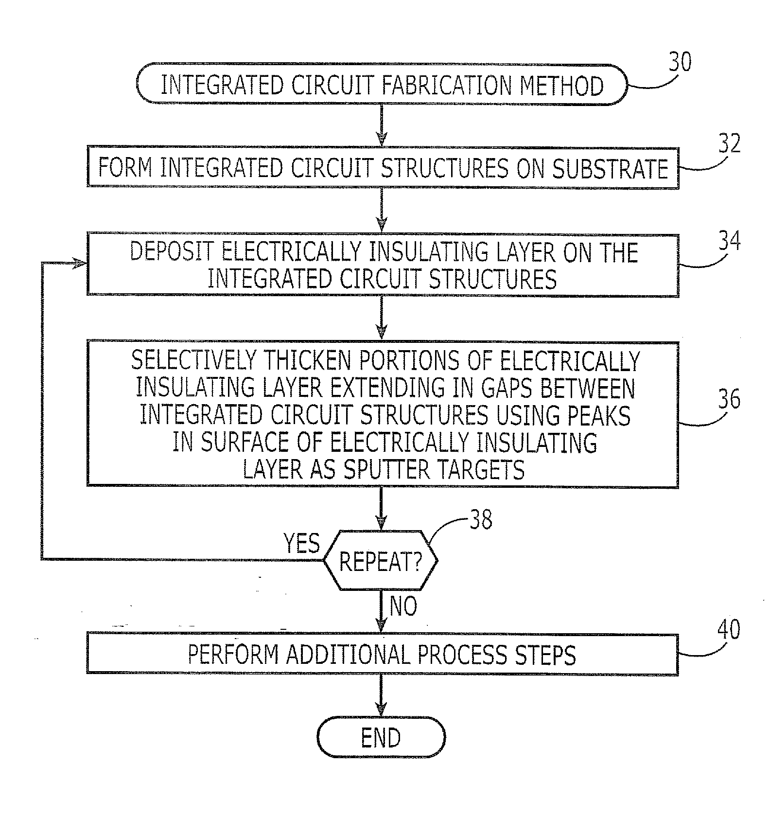
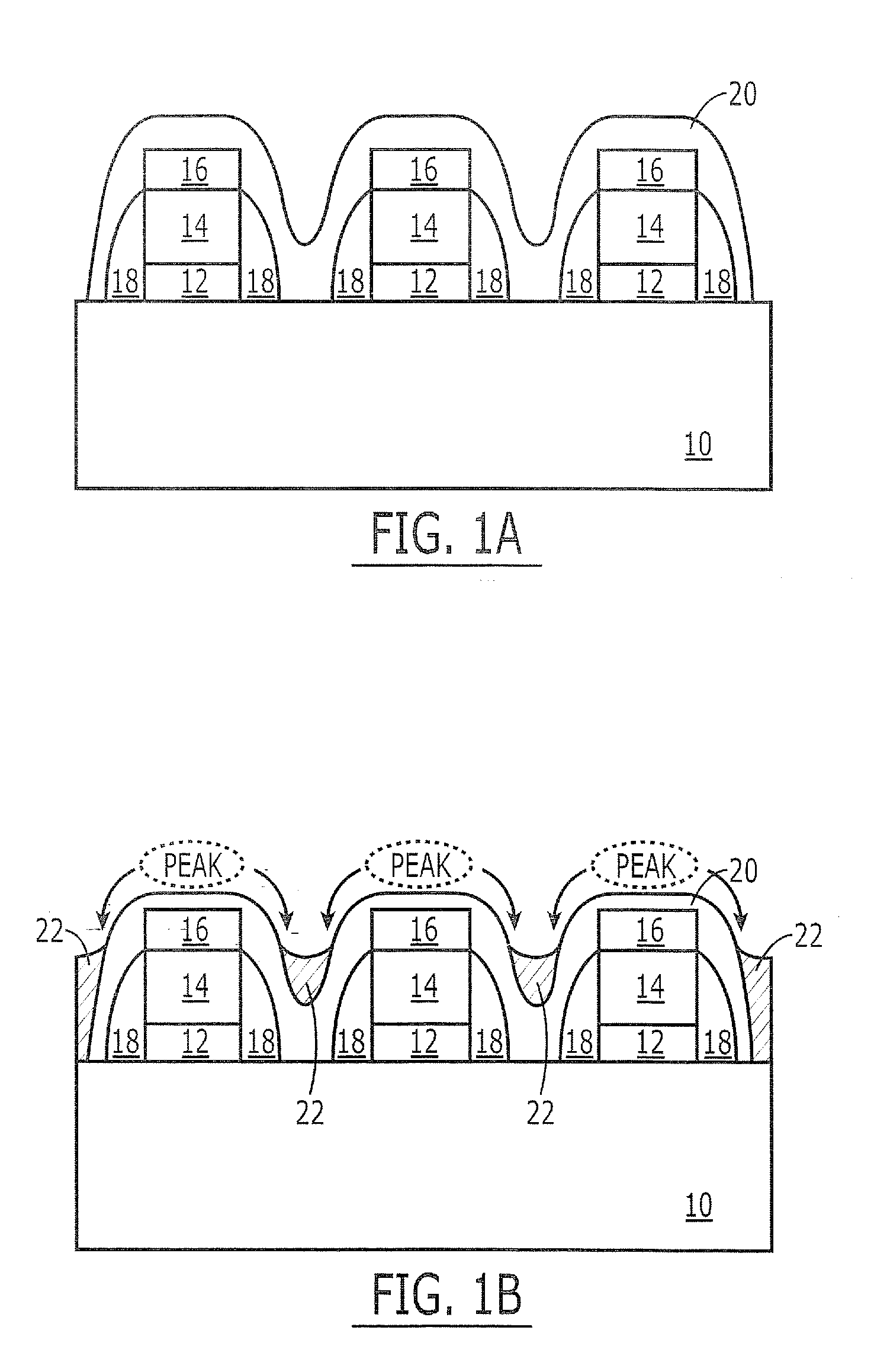
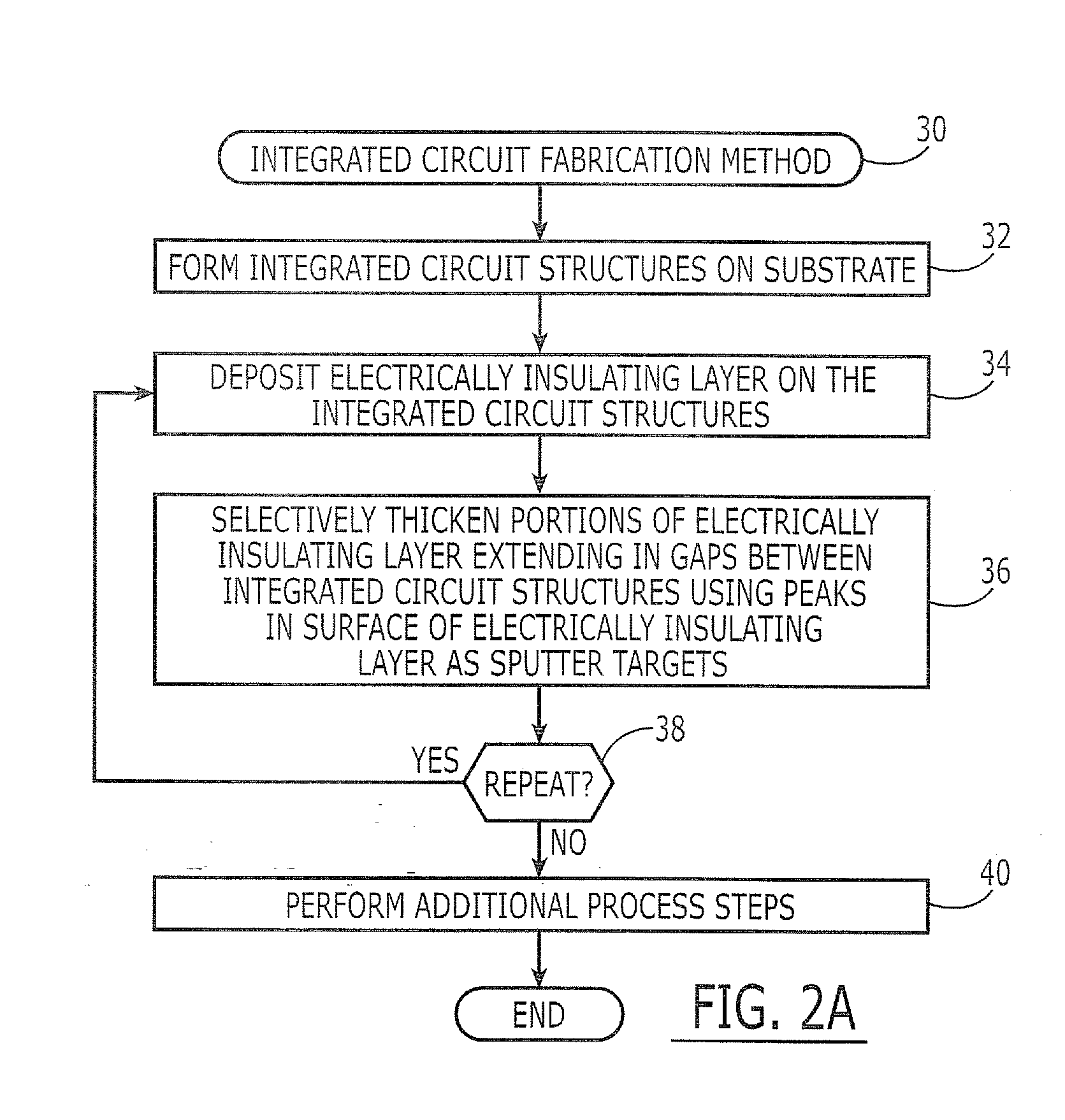
[0012]FIGS. 1A-1B illustrate methods of forming integrated circuit devices according to first embodiments of the present invention. As illustrated by FIG. 1A, a plurality of integrated c...


PUM

PropertyMeasurementUnit
Poweraaaaaaaaaa
Concentrationaaaaaaaaaa
aaaaaaaaaa

Abstract

Methods of forming integrated circuit devices include depositing an electrically insulating layer onto an integrated circuit substrate having integrated circuit structures thereon. This deposition step results in the formation of an electrically insulating layer having an undulating surface profile, which includes at least one peak and at least on valley adjacent to the at least one peak. A non-uniform thickening step is then performed. This non-uniform thickening step includes thickening a portion of the electrically insulating layer by redepositing portions of the electrically insulating layer from the least one peak to the at least one valley. This redeposition occurs using a sputter deposition technique that utilizes the electrically insulating layer as a sputter target.

Description

FIELD OF THE INVENTION[0001]The present invention relates to integrated circuit fabrication methods and, more particularly, to methods of fabricating field effect transistors in integrated circuit substrates.BACKGROUND OF THE INVENTION[0002]Conventional techniques to increase the levels of device integration on integrated circuit substrates can often lead to reductions in device yield and device reliability. Some of these reductions in device yield may be caused by the formation of voids or gaps within electrically insulating layers and also within electrical interconnects that may extend through one or more electrically insulating layers. In particular, the conformal deposition of relatively thick electrically insulating layers on closely-spaced integrated circuit structures having relatively narrow aspect ratios may lead to the formation of voids in the spaces between the integrated circuit structures. These voids can result in the formation of electrical shorts between electrical...

Claims


Application Information

Patent Timeline
IPC IPC(8): H01L29/82
CPCC23C16/56H01L21/31051H01L21/3185H01L21/823425H01L21/76829H01L21/76837H01L21/76826H01L21/02266H01L21/02274H01L21/02211H01L21/0217H01L21/203H01L21/31
Inventor KIM, JUN-JUNGKU, JA-HUMPARK, JAE-EONFANG, SUNFEIGUTMANN, ALOISKWON, O-SUNGWIDODO, JOHNNYYANG, DAE-WON
Owner SAMSUNG ELECTRONICS CO LTD
Why Eureka
Try Eureka