Automated engine data diagnostic analysis

a technology of engine data and diagnostic analysis, applied in the direction of instruments, testing/monitoring control systems, process and machine control, etc., can solve the problems of time delays and/or other costs of time and/or money, experienced engineers may not be readily available to assess the fault root, test cell technicians may not possess the expertise or experience to perform fault isolation and repair efforts in an efficient and optimal manner,

Inactive Publication Date: 2008-09-18
HONEYWELL INT INC
View PDF5 Cites 53 Cited by
  • Summary
  • Abstract
  • Description
  • Claims
  • Application Information

AI Technical Summary

Benefits of technology

[0006]The present invention provides a method for diagnosing potential faults reflected in operational data for a turbine engine. In one embodiment, and by way of example only, the method comprises the steps of generating a diagnostic pattern for the operational data and comparing the diagnostic pattern with a plurality of historical patterns, to thereby identify one or more likely potential faults reflected in the operational data. The diagnostic pattern comprises a plurality of scalars. Each scalar represents an arithmetic relationship between values of the operational data and values predicted by a baseline thermodynamic model that represents the average engine performance. Each historical pattern is linked to one or more specific faults.
[0007]The invention also provides a program product for diagnosing potential faults reflected in operational data for a turbine engine. In one embodiment, and by way of example only, the program product comprises a program, and a computer-readable signal bearing media bearing the program. The program is configured to generate a diagnostic pattern for the operational data, and compare the diagnostic pattern with a plurality of historical patterns, to thereby identify one or more likely potential faults reflected in the operational data. The diagnostic pattern comprises a plurality of scalars. Each scalar represents an arithmetic relationship between values of the operational data and values predicted by a baseline thermodynamic model. Each historical pattern is linked to one or more specific faults.
[0008]In another embodiment, and by way of example only, the program product comprises a program, and a computer-readable signal bearing media bearing the program. The program is configured to generate a matrix of operating parameter perturbations to simulate a plurality of engine faults, run the matrix through the baseline thermodynamic model, to thereby generate a historical pattern for each fault, generate a diagnostic pattern for the operational data, compare the diagnostic pattern with a plurality of historical patterns, to thereby identify multiple likely potential faults based at least in part on the comparison of the diagnostic pattern with the plurality of historical patterns, assign probability values to each of the identified likely potential faults based at least in part on the comparison between the diagnostic pattern and the plurality of historical patterns, each probability value representing a probability that the engine has a particular fault, and generate user instructions for further diagnosis of the multiple likely potential faults, based at least in part on the assigned probability values. The diagnostic pattern comprises a plurality of scalars. Each scalar represents an arithmetic relationship between values of the operational data and values predicted by the baseline thermodynamic model. Each historical pattern is linked to one or more specific faults, and represents a deviation from the baseline thermodynamic model resulting from the fault. Each likely potential fault has a different historical pattern.

Problems solved by technology

In many cases an experienced engineer may not be readily available to assess the fault root cause and provide guidance on corrective action.
Test cell technicians, while generally well qualified, may not possess the expertise or experience to perform fault isolation and repair efforts in an efficient and optimal manner.
Accordingly, such test cell technicians may perform such fault isolation and repair efforts in a manner that is inefficient and / or otherwise less than optimal, or may choose to wait for the availability of engineering personnel, which can result in time delays and / or other costs of time and / or money.

Method used


Image

  • Automated engine data diagnostic analysis
  • Automated engine data diagnostic analysis
  • Automated engine data diagnostic analysis

Examples


Embodiment Construction

[0021]Before proceeding with the detailed description, it is to be appreciated that the described embodiment is not limited to use in conjunction with a particular type of turbine engine, or to turbine engines in general. Thus, although the present embodiment is, for convenience of explanation, depicted and described as being implemented in connection with a turbine engine, it will be appreciated that it can be implemented in connection with various other devices, systems, and / or environments.

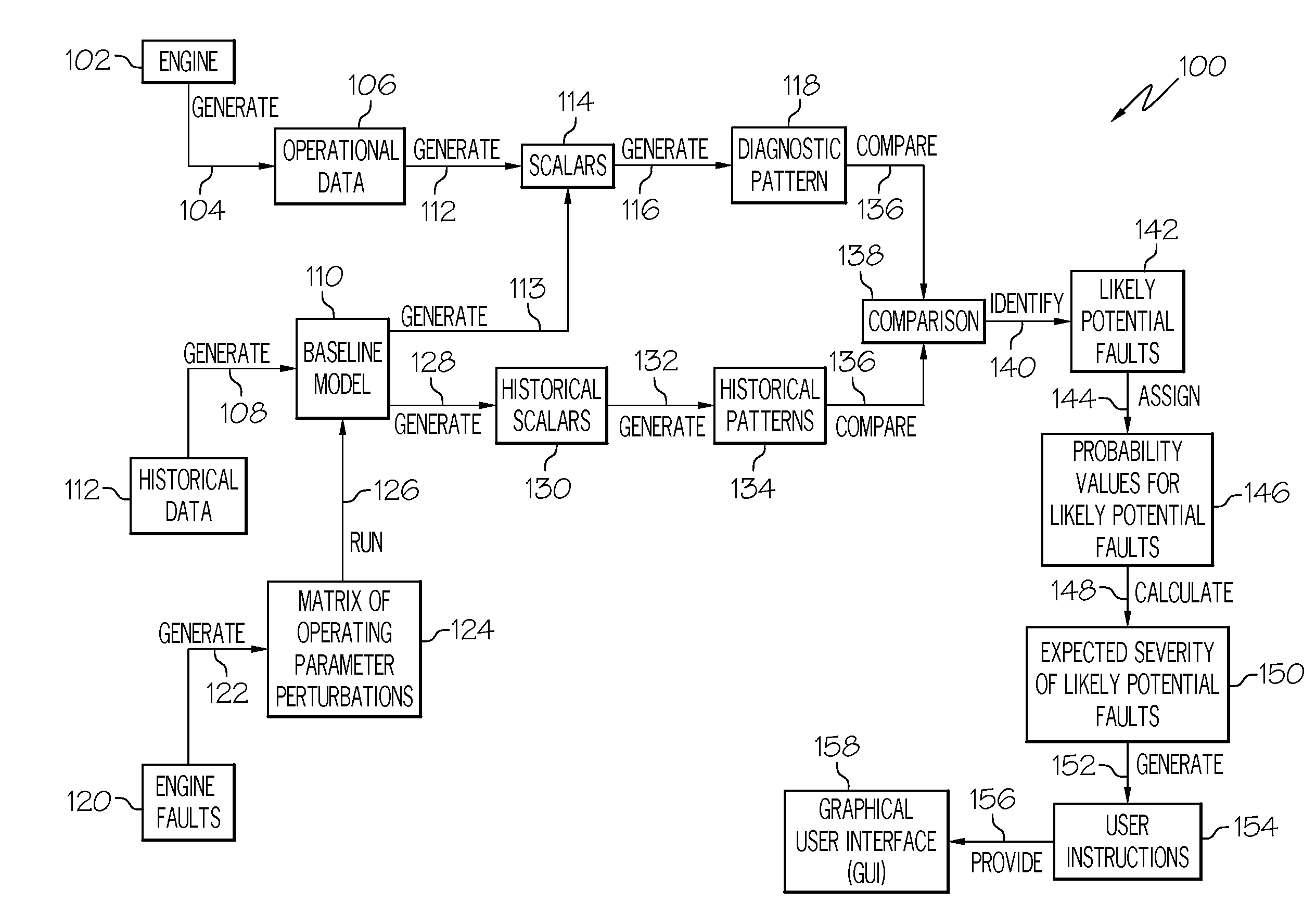
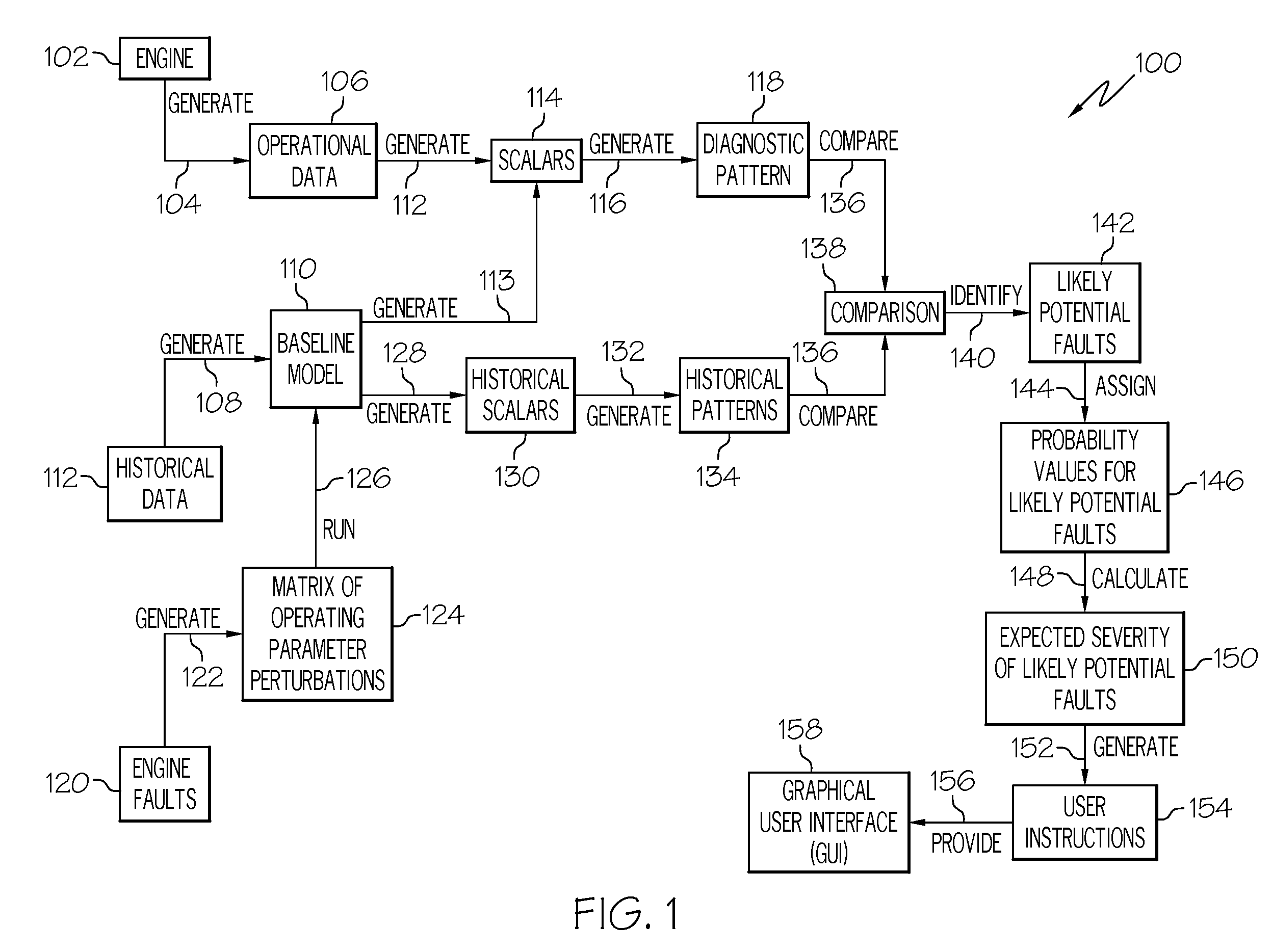
[0022]FIG. 1 depicts an exemplary embodiment of a diagnostic process 100 for diagnosing potential faults reflected in operational data 106 for a turbine engine 102 undergoing testing. As depicted in FIG. 1, the diagnostic process 100 begins with step 104, in which the operational data 106 is generated. The turbine engine 102 may be undergoing testing because it has been recently manufactured, repaired, or overhauled, or for any one of a number of other reasons. The operational data 106 preferab...


PUM


Abstract

A method for diagnosing potential faults reflected in operational data for a turbine engine includes the steps of generating a diagnostic pattern for the operational data and comparing the diagnostic pattern with a plurality of historical patterns, to thereby identify one or more likely potential faults reflected in the operational data. The diagnostic pattern comprises a plurality of scalars. Each scalar represents an arithmetic relationship between values of the operational data and values predicted by a baseline thermodynamic model. Each historical pattern is linked to one or more specific faults.

Description

FIELD OF THE INVENTION[0001]The present invention relates to gas turbine engines and, more particularly, to improved methods and apparatus for analyzing engine operational data and potential faults represented therein.BACKGROUND OF THE INVENTION[0002]Gas turbine engines routinely undergo an acceptance test procedure before being delivered to a customer. This applies to newly manufactured gas turbine engines, as well as repaired or overhauled gas turbine engines. Typically the new, repaired, or overhauled gas turbine engine must pass the acceptance test procedure before delivery. Generally, the acceptance test procedure includes a performance calibration that generates data and an acceptance test data certificate that is a quality record used to ensure compliance with customer specifications.[0003]In a gas turbine production, repair, or overhaul environment, rapid diagnostic analysis of engine performance anomalies or faults, should they occur, may be required to meet stringent deliv...

Claims


Application Information

Patent Timeline
Patent Type & Authority Applications(United States)
IPC IPC(8): G01M17/00
CPCG05B23/0278G05B23/0254
Inventor HOWARD, JOSEPH S.STRAMIELLO, ANDREW D.
Owner HONEYWELL INT INC
Why Eureka
Try Eureka