Engagement fitting and manufacturing method of engagement fitting

Inactive Publication Date: 2008-09-25
NISHIO SEIMITSU KK
View PDF13 Cites 6 Cited by
  • Summary
  • Abstract
  • Description
  • Claims
  • Application Information

AI Technical Summary

Benefits of technology

[0008]Because the conventional striker comprises multiple parts, the assembling man-hours increase. Moreover, it also is required to strengthen the attachment portions of the multiple parts. Therefore, one aspect of an embodiment of the present in

Problems solved by technology

Therefore, the manufacturing process is fairly complicated and fairly costly.
However, because the engagement pestle is formed of a la

Method used


Image

  • Engagement fitting and manufacturing method of engagement fitting
  • Engagement fitting and manufacturing method of engagement fitting
  • Engagement fitting and manufacturing method of engagement fitting

Examples


Example

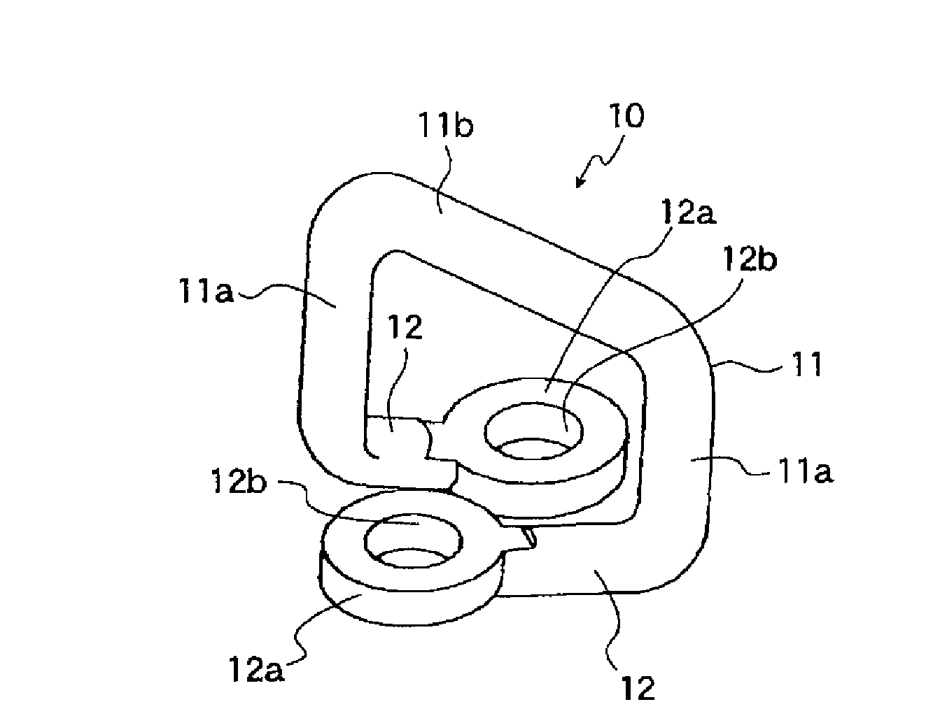
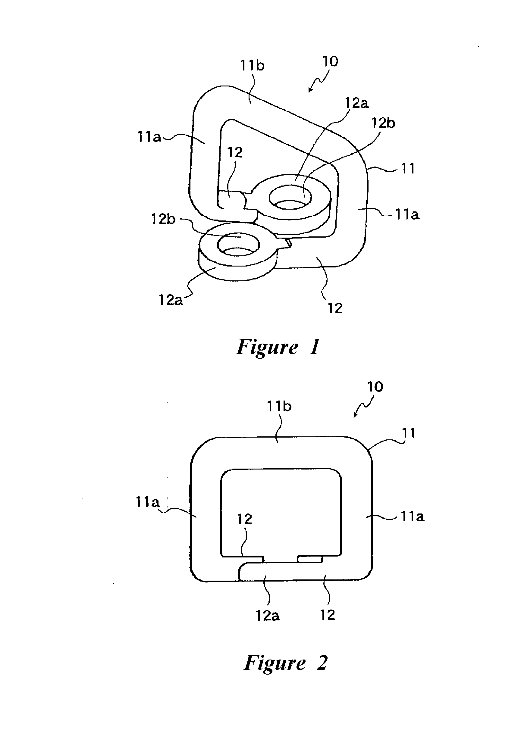
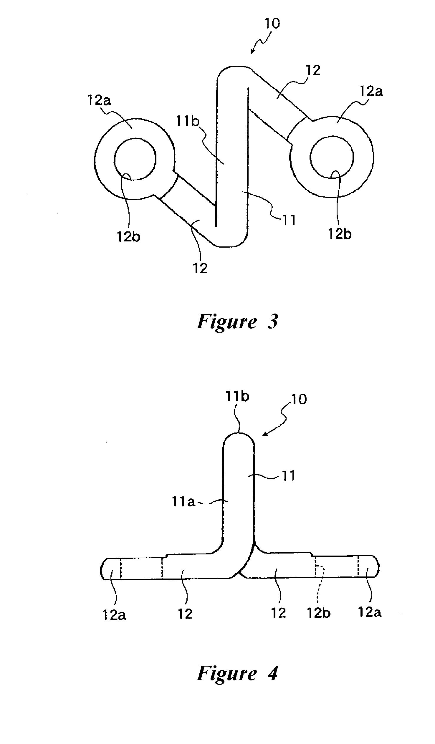
[0037]With reference now to FIGS. 1-6, a strike plate or engagement fitting 10 is shown. The engagement fitting 10 can be used with an automobile door as an “opening-and-closing body.” The illustrated engagement fitting 10 comprises a hook 11 that is integrally shaped from a single metal rod member. The engagement fitting 10 preferably is bent generally in a gate shape (i.e., bent in a generally U-shaped configuration). The engagement fitting 10 also comprises bases 12 that are bent at an approximately right angle at base ends of a pair of legs 11a of the generally U-shaped hook 11. The bases 12 preferably extend in opposite directions from one another across a plane that is generally defined by the generally U-shaped hook 11.

[0038]The hook 11 comprises a pair of the legs 11a and an engagement pestle 11b that extends across these legs 11a. The engagement pestle 11b preferably extends generally parallel with a surface (not shown) of a vehicle body on which the engagement fitting 10 w...


PUM

PropertyMeasurementUnit
Lengthaaaaaaaaaa
Angleaaaaaaaaaa

Abstract

An engagement fitting comprises a hook that is integrally formed from a metal rod member. The rod member is bent into a generally U-shaped configuration. Bases then can be bent at approximately right angles at base ends of a pair of legs of the generally U-shaped hook. The bases extend to opposite sides from one another across a plane that is generally defined by the U-shaped configuration. The base is formed at least partially flat and can be provided with attachments such that the engagement fitting can be mounted on other members.

Description

CROSS-REFERENCE TO RELATED APPLICATIONS[0001]This application claims the prior benefit under 35 USC 119 of Japanese Patent Application No. 2007-75994, filed Mar. 23, 2007, Japanese Patent Application No. 2007-121605, filed May 2, 2007, and Japanese Patent Application No. 2007-258968, filed Oct. 2, 2007, each of which is hereby incorporated by reference in its entirety.BACKGROUND OF THE INVENTION[0002]1. Field of the Invention[0003]The present invention relates to an engagement fitting used as a locking device striker for an opening-and-closing body (e.g., door) of, for example, a vehicle interior, an engine compartment, a trunk, or the like of an automobile; and a method of manufacturing the engagement fitting.[0004]2. Description of the Related Art[0005]With reference initially to FIGS. 25 and 26, an “engagement fitting” generally is paired with an engagement pawl that is controlled by a device, such as a key and a lever. The engagement fitting can be made by bending into a U-shape...

Claims


Application Information

Patent Timeline
IPC IPC(8): E05C19/10B21F45/16
CPCB21F45/00Y10T29/49716E05B85/045Y10T292/087Y10T292/68Y10T292/683
Inventor NISHIO, MAYUKINISHIO, SHINICHINISHIO, MASAYUKINISHIO, TATSUYA
Owner NISHIO SEIMITSU KK
Why Eureka
Try Eureka