Vehicle maneuvering aids

a technology for maneuvering and vehicles, applied in the direction of trailer steering, television systems, instruments, etc., can solve the problem that only monitors the electrical connection of trailers cannot distinguish between trailers and light bars

Inactive Publication Date: 2008-09-25
FORD GLOBAL TECH LLC
View PDF99 Cites 249 Cited by
  • Summary
  • Abstract
  • Description
  • Claims
  • Application Information

AI Technical Summary

Benefits of technology

[0006]A third feature tracks obstacles close to the path of a vehicle using multiple vehicle-mounted video cameras with pan and zoom capability. One method of tracking these obstacles includes the steps of detecting the proximity of an obstacle using a vehicle-mounted proximity sensor, panning a vehicle-mounted video camera towards the location of the obstacle, and displaying a video camera view of the obstacle to a driver of the vehicle. A fourth feature reliably informs the vehicle and driver when a trailer is hitched to the vehicle. This is so that systems concerned with dynamic stability control or active suspension, e.g. can be set to the correct operating conditions. Systems that only monitor the trailer's electrical connection cannot distinguish between a trailer and light

Problems solved by technology

Systems that only monitor the trailer's electrical connec

Method used


Image

  • Vehicle maneuvering aids
  • Vehicle maneuvering aids
  • Vehicle maneuvering aids

Examples


first embodiment

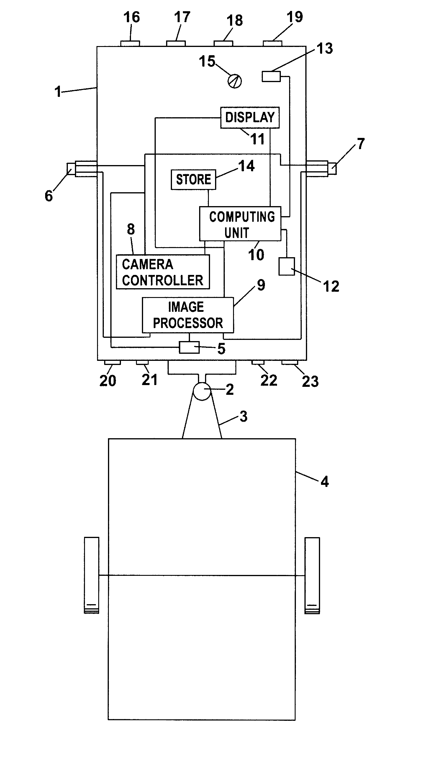
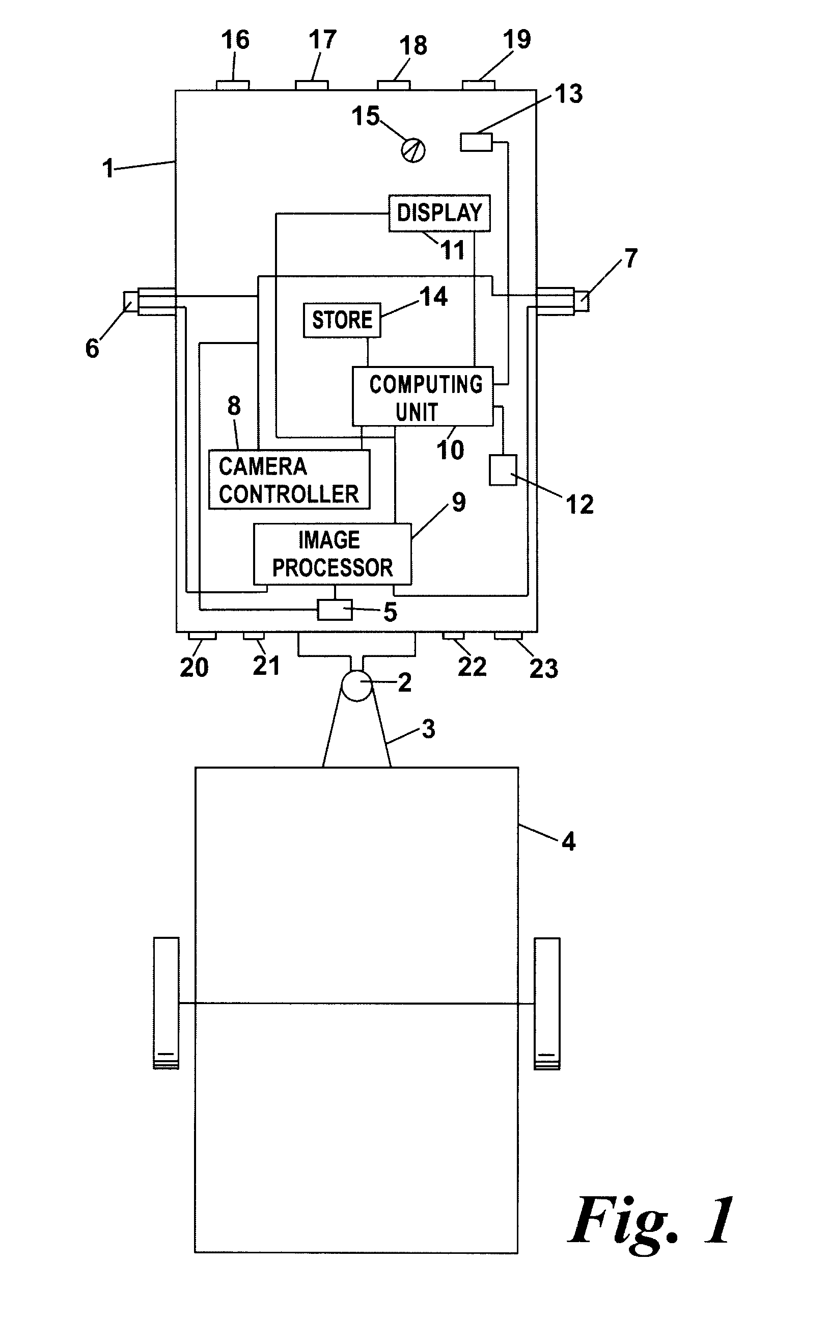
[0014]Operation of a first embodiment, comprising a method of measuring the hitch angle (in a horizontal plane between the vehicle 1 and the trailer 4) will now be described with reference to FIGS. 1 and 2. The method utilizes a tracking marker such as a mark or sticker attached to the trailer or a vertical edge of the trailer which is visible to the rearward-looking video camera 5. The image processor 9 locates this marker within the camera's field of view and feeds this information to the computing unit 10 which calculates the hitch angle.

[0015]In a first example, a high visibility marker 24 is placed on the centre-line of the trailer 4 (see FIG. 2). From knowledge of the trailer and vehicle geometric parameters e.g. tow hitch length (held in the store 14) and the position of the marker within the camera's 5 field of view, the computing unit 10 can calculate the hitch angle θt. Placement of the marker on the trailer's centre-line may not always be possible or convenient. So in a s...

second embodiment

[0022]the invention provides a method of predicting a trailer reversing path and displaying it to the driver by means of an overlay on the display.

[0023]Say, for example, the driver needs to reverse the vehicle and trailer combination into a parking bay.

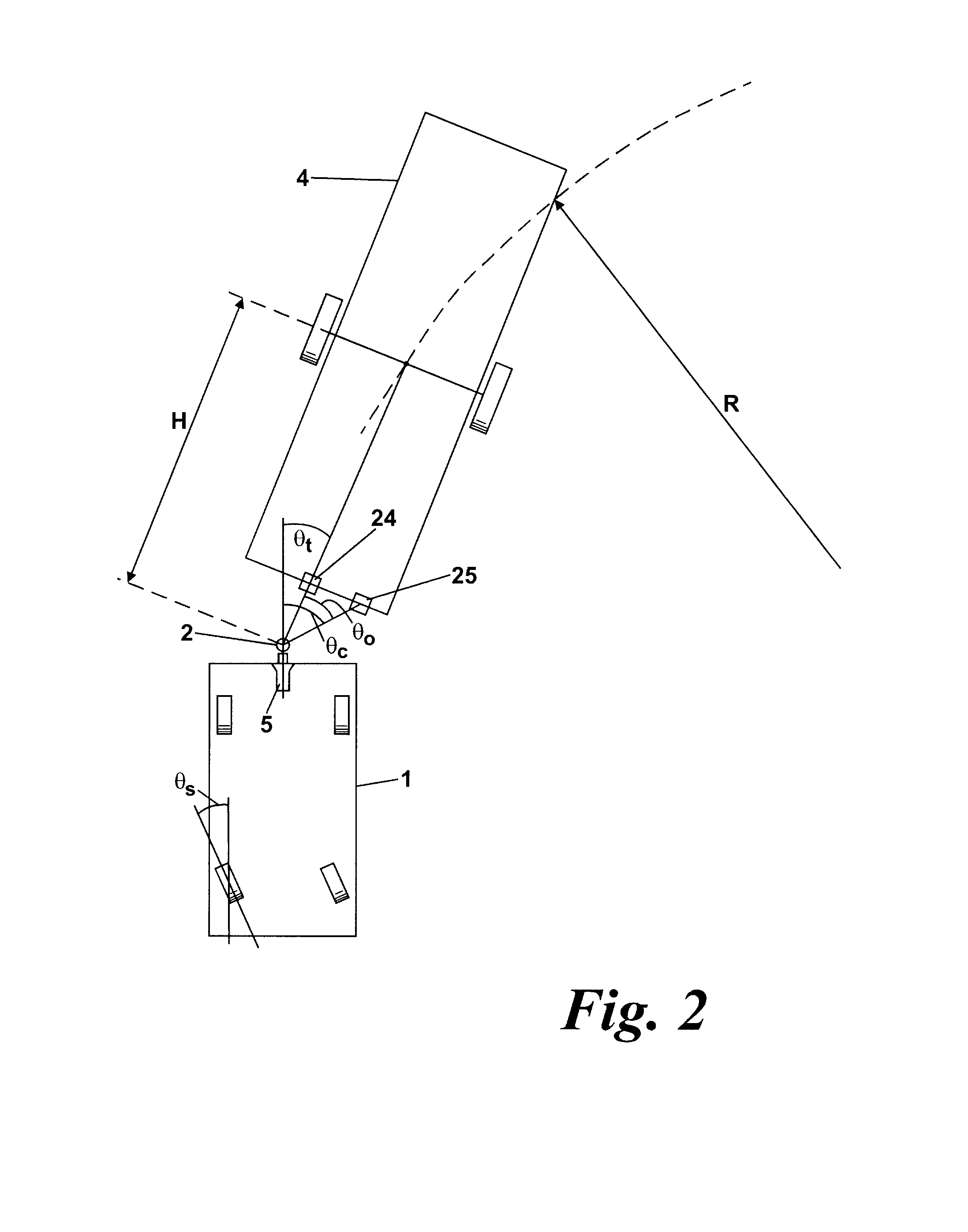
[0024]Knowing the hitch angle θt, (either from the method of the first embodiment described above or from some other method or sensor output), and the hitch length H (the distance between the trailer's axle and tow hitch, see FIG. 3) the computing unit 10 computes a trailer path.

[0025]The path of the trailer 4 can be described by a turning radius R. In practice R and θt vary during the maneuver but for small steering angle movements can be assumed to be constant. With reference to FIG. 3, it can be seen that the hitch angle θt, hitch length H and turning radius R are associated approximately by equation:

α+β+δ=π

[0026]Substituting β=π / 2 and α=π / 2−θt

[0027]gives θt=δ

[0028]tan δ=H / R=δ=θt for small θt

So R=H / θt (θt in radians)   Equation ...

third embodiment

[0038]Operation of the invention, which facilitates the tracking of obstacles, will now be described.

[0039]In this example, the door mirror mounted cameras 6, 7 are triggered by one or more of the parking distance sensors 16-19 when the vehicle comes within close range of an object. On the display screen 11, the driver will be presented with a view of the obstacle and a part of the exterior of the vehicle closest to it.

[0040]In an off-road or other tight maneuvering situation, the driver may want to continue to observe the object while driving past it. For example, while driving past a boulder, the driver will want to ensure that the boulder is not contacted by the side of the vehicle.

[0041]Clearly it is possible for the driver to manually control the camera to adjust its aim while driving past the object. However, this requires intervention by the driver and may distract him / her from other driving tasks.

[0042]This embodiment makes use of the ability of the cameras 6, 7 to pan and z...


PUM


Abstract

A vehicle 1 towing a trailer 4 is fitted with three video cameras 5, 6, 7 fitted to the rear of the vehicle and on each door mirror. A view from any camera can be presented to the driver on a display 11. A predicted trailer path, calculated in a computing unit 10, is also presented to the driver on the display 11 as guide lines overlaid on the camera view. The computing unit 10 is also configured to calculate a hitch angle by tracking the position of a trailer-mounted marker in the camera view.

Description

CROSS-REFERENCE TO RELATED APPLICATIONS[0001]NoneBACKGROUND OF THE INVENTION[0002]This invention relates to maneuvering aids for vehicles and particularly for vehicles which are towing a trailer, such as a caravan.[0003]It is known to equip vehicles with external video cameras for displaying to the driver an image of the surroundings in order to provide assistance with parking and reversing maneuvers. A track for a given steering angle can be superimposed on the displayed image including systems that display the view from a rearward-looking video camera onto a touch screen which is used to input a desired destination, such as a parking bay. Steering cues are also displayed on the screen for assisting the driver in the maneuvering operation.BRIEF DESCRIPTION OF THE INVENTION[0004]A first feature provides a method for determining hitch angle in a vertical or horizontal plane between a vehicle and a trailer attached to the vehicle by means of a tow hitch. The method includes the steps ...

Claims


Application Information

Patent Timeline
IPC IPC(8): H04N7/18
CPCB60R1/00B60R2300/101B60R2300/301B60R2300/305B60R2300/806B60R2300/8093G08G1/167B62D15/024G01B11/272G06T7/0008G06T7/20G08G1/16B62D13/06G08G1/166G08G1/168G06T7/70B60D1/58B60R1/003B62D15/029G01B11/26G06V20/56H04N23/54B60R2300/108B60R2300/50B60R2300/802B60R2300/8086H04N7/183B60W50/14B60W2050/143B62D15/021
Inventor GREENWOOD, JEREMY JOHNNICHOLLS, STEPHENCRAWFORD, ANDREW STEPHEN BELL
Owner FORD GLOBAL TECH LLC
Why Eureka
Try Eureka