Liquid storage container and liquid storage body-receiving mamber

a liquid storage container and liquid storage technology, applied in printing and other directions, can solve the problems of inability to attach piezoelectric devices to ink cartridges, inability to sell ink-full states, and difficulty in detachment of piezoelectric devices from ink cartridges

Inactive Publication Date: 2008-10-02
SEIKO EPSON CORP
View PDF2 Cites 11 Cited by
  • Summary
  • Abstract
  • Description
  • Claims
  • Application Information

AI Technical Summary

Benefits of technology

[0018]According to another aspect of the present invention, there is provided a liquid storage body-receiving member configured as a body separate from a liquid storage body having a liquid storage portion for storing liquid therein, including: a liquid storage body-receiving portion that detachably receives the liquid storage body; and a detection sensor that is used in detecting the liquid within the liquid storage portion when the liquid storage body is attached. When the liquid s...

Problems solved by technology

In view of these points, although the piezoelectric device is in fact detachably attached to the ink cartridge, it is necessarily hard to detach the piezoelectric device from the ink cartridge.
Because of the opening, the cartridge cannot have ink in it prior to the attachment of the piezoelectric device because the ink would undesirably come out of the opening.
That i...

Method used


Image

  • Liquid storage container and liquid storage body-receiving mamber
  • Liquid storage container and liquid storage body-receiving mamber
  • Liquid storage container and liquid storage body-receiving mamber

Examples


first modified example

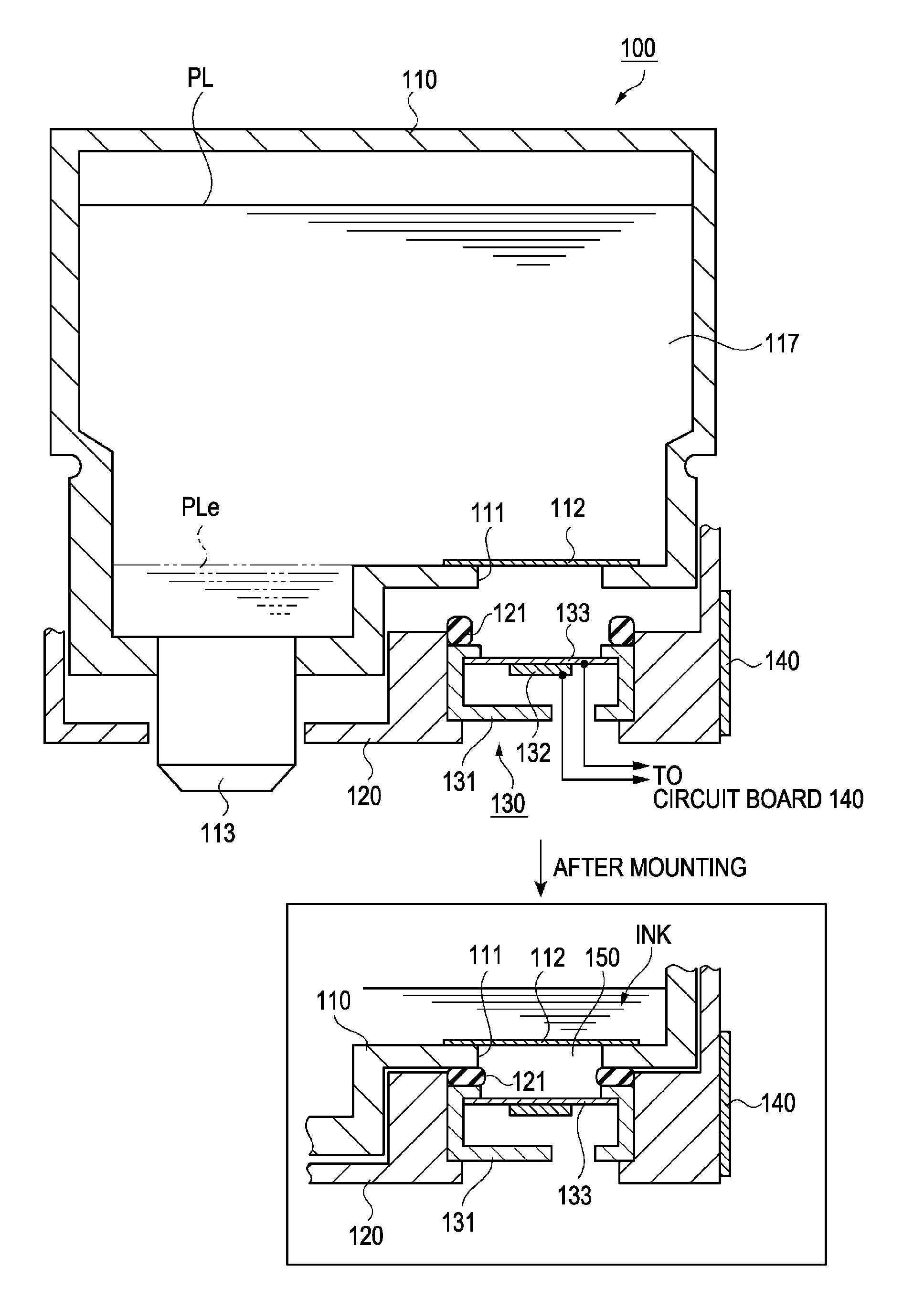
[0049]In the embodiment described above, as shown in FIG. 3, the sheet member 112 is fixed to the bottom sidewall which is in the gravitational direction with respect to the ink container body 110, and the ink is abutting on the sheet member 112 in the direction (gravitational direction) from the upper side to the lower side in the drawing. However, the ink cartridge may have a different configuration. For example, as shown in FIG. 4, an ink cartridge 100a is configured such that an ink container body 110a is attached to a detection container body 120a in the horizontal direction of the drawing (a direction substantially perpendicular to the gravitational direction).

[0050]In this modified example, in the ink container body 110a, an opening portion 111a is formed in a sidewall of the liquid storage portion 117a, the sidewall being in the direction substantially perpendicular to the gravitational direction. In the opening portion 111a, a sheet member 112a of which the outer periphery ...

second modified example

[0055]In the embodiment described above, the vibration of the vibration plate 133 of the detection sensor 130 and the vibration of the sheet member 112 are coupled via the air spring that uses the air confined in the space 150. Although an air spring may be used to great advantage, the use of an air spring can be omitted in favor of a direct coupling arrangement; the vibration of the vibration plate 133 and the vibration of the sheet member 112 may be directly coupled without the air spring. This modified example will be described with reference to FIGS. 5A and 5B.

[0056]FIG. 5A is a sectional view showing some parts of an ink cartridge 100b according to this modified example. According to the ink cartridge of the present modified example, like the above-described embodiment shown in FIG. 3, has a two-body structure in which an ink container body 110b is attached to a detection container body 120b from the upper part of the drawing.

[0057]Like the embodiment described above, in this m...


PUM


Abstract

A liquid storage container is provided which is configured to be detachable from a liquid ejecting apparatus. The storage container includes a liquid storage body having a liquid storage portion for storing liquid therein, a liquid storage body-receiving member configured as a separate body from the liquid storage body and detachably receiving the liquid storage body, and a detection sensor provided to the liquid storage body-receiving member and used in detecting the liquid within the liquid storage body.

Description

BACKGROUND[0001]1. Technical Field[0002]The present invention relates to a liquid storage container that stores liquid, and to a liquid storage body-receiving member that constitutes part of the liquid storage container.[0003]2. Related Art[0004]A liquid ejecting apparatus forms predetermined characters, figures or images (hereinafter, collectively referred to as “images”) on a printing sheet, a glass substrate, or a resin substrate. In a liquid ejecting apparatus, liquid stored in a liquid storage container is ejected from an ejecting head onto a medium to form predetermined images on the medium (the medium may be thought of more generally as an ejection subject). One example of such a liquid ejecting apparatus ejects ink, as the liquid, onto a printing sheet, as the ejection subject, to form predetermined images on the printing sheet.[0005]Ink jet printers of this type are configured such that ink is supplied to an ejecting head from an ink cartridge, serving as a liquid storage c...

Claims


Application Information

Patent Timeline
IPC IPC(8): B41J2/175
CPCB41J2/17566B41J2002/17583
Inventor YOSHIMOTO, TADAYUKIKOSHINO, KAZUO
Owner SEIKO EPSON CORP
Why Eureka
Try Eureka