
Image forming apparatus

a technology of image forming apparatus and cooling chamber, which is applied in the direction of electrographic process apparatus, instruments, optics, etc., can solve the problems of inability to exhibit a significant performance improvement worth the cost of providing the fan, inability to sufficiently cool a hot recording sheet, and unstable behavior, etc., to achieve sufficient cooling and stabilize the behavior

Inactive Publication Date: 2008-10-02
KYOCERA DOCUMENT SOLUTIONS INC
View PDF6 Cites 11 Cited by
  • Summary
  • Abstract
  • Description
  • Claims
  • Application Information

AI Technical Summary

Benefits of technology

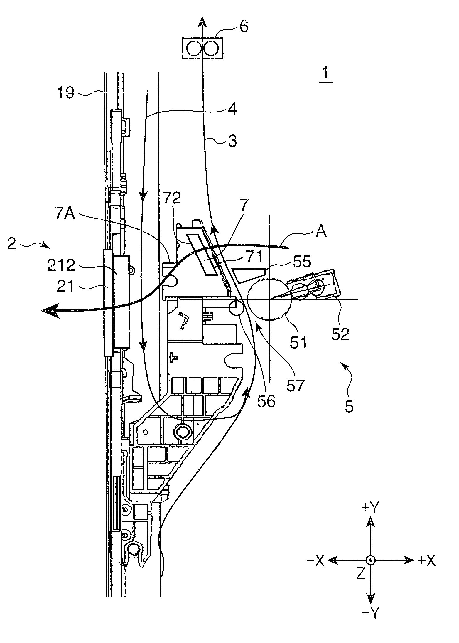
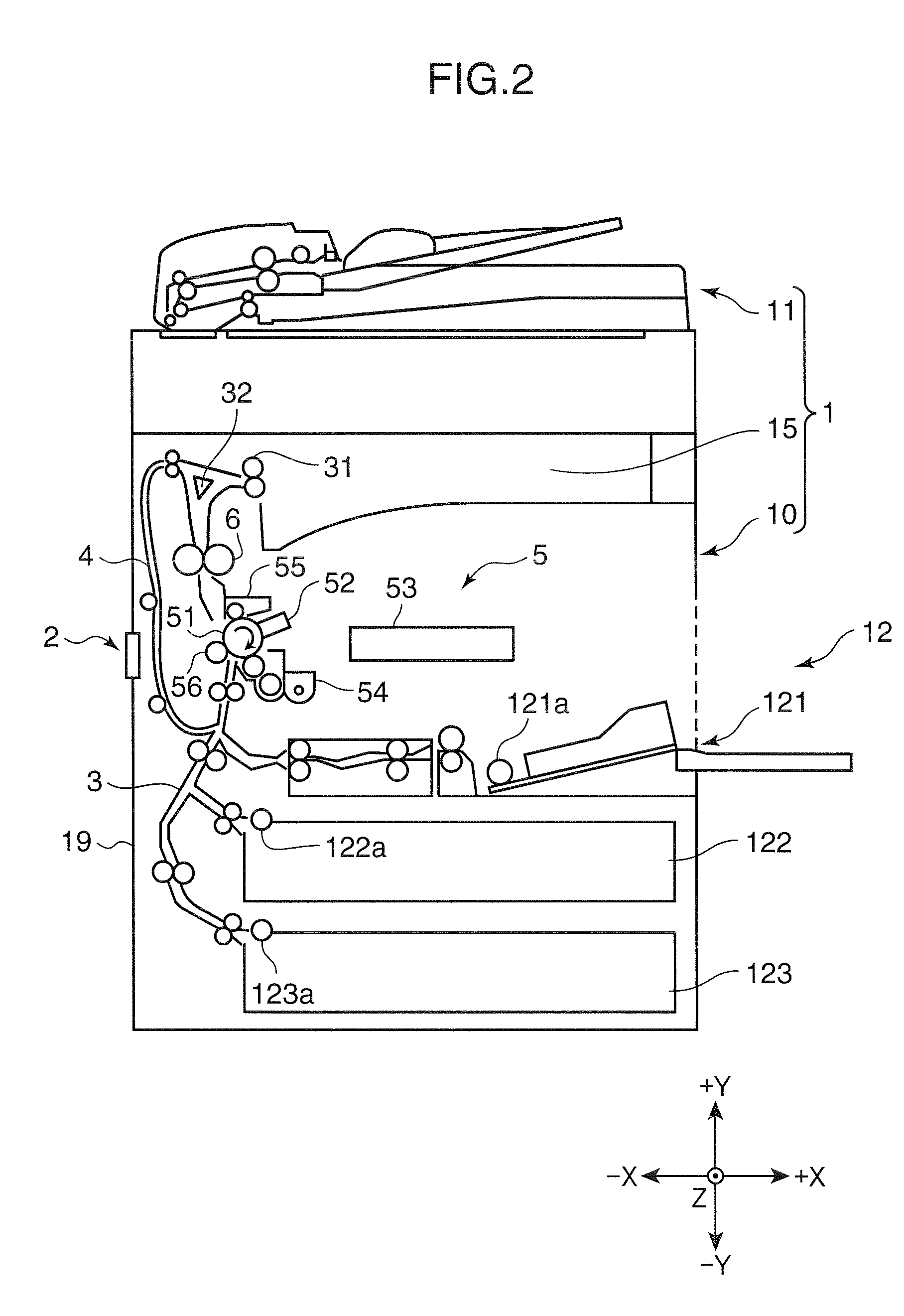
The present invention aims to provide an image forming apparatus that can cool down a recording material that has reached a high temperature during duplex printing and stabilize its behavior in the first conveyance path. The apparatus includes an image forming unit, a fixing unit, and two conveyance paths. One conveyance path is used for conveying the recording material through the image forming unit and the fixing unit, while the other conveyance path is used for returning the recording material back to the upstream side of the image forming unit. A fan is placed between these two conveyance paths to create an air stream that can cool down the recording material on the first conveyance path while heating it on the second conveyance path. This invention helps to improve the quality and stability of the image forming process.

Problems solved by technology

H07-239647 uses the common fan and has a problem of being unable to sufficiently cool a hot recording sheet.
Further, technology disclosed in Japanese Unexamined Patent Publication No. 2000-304395 cannot exhibit a significant performance improvement worth the cost of providing the fan since the special fan for the second conveyance path for cooling only the vicinity of the second conveyance path is used.
On the other hand, image forming apparatuses have had a problem that a recording sheet being conveyed in the first conveyance path is, for example, lifted from the conveyance path to make its behavior unstable.

Method used


Image

  • Image forming apparatus
  • Image forming apparatus
  • Image forming apparatus

Examples


Embodiment Construction

[0016]Hereinafter, one embodiment of the present invention is described in detail with reference to the accompanying drawings.

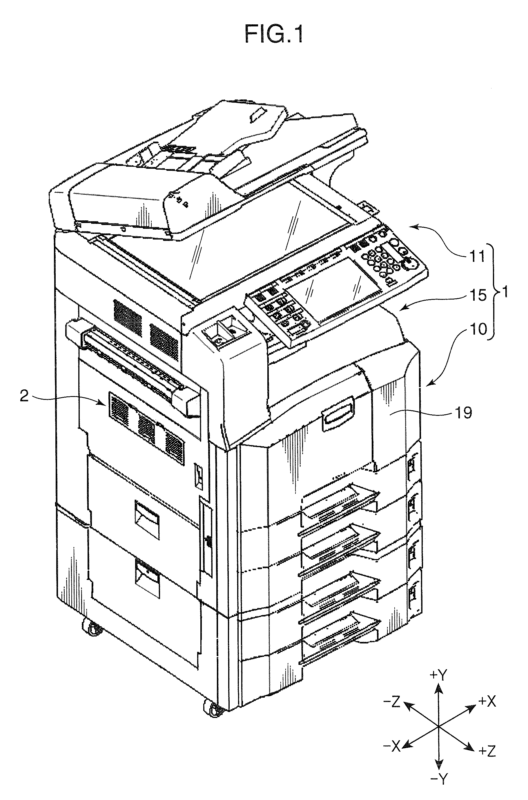
[0017]FIG. 1 is a perspective view showing the external appearance of an image forming apparatus 1 according to one embodiment of the invention. The image forming apparatus 1 is a copier of the so-called internal discharge type provided with an apparatus main body 10, a scanner unit 11 arranged atop the apparatus main body 10 and a discharge unit 15 arranged between the apparatus main body 10 and the scanner unit 11.

[0018]Various mechanisms used for image formation are accommodated in the apparatus main body 10 (to be described later with reference to FIG. 2). An outer covering 19 of the image forming apparatus 10 constitutes the outer body of the apparatus main body 10 and functions as a casing for accommodating various mechanisms of the apparatus main body 10 used for image formation. A plurality of sheet cassettes (see sheet cassettes 122, 123 shown in FIG...


PUM


Abstract

An image forming apparatus is provided with an image forming unit for applying an image transferring process to a sheet-like recording material, a fixing unit for applying a heat fixing process to the recording material after the image transferring process by the image forming unit, a first conveyance path for conveying the recording material via the image forming unit and the fixing unit, a second conveyance path for returning the recording material after the fixing process by the fixing unit to an upstream side of the image forming unit from a side of the first conveyance path downstream of the fixing unit in the case of applying the image transferring process to both sides of the recording material, and a fan disposed between the first and second conveyance paths for taking air across the first conveyance path and exhausting air across the second conveyance path to form an air stream.

Description

BACKGROUND OF THE INVENTION[0001]1. Field of the Invention[0002]The present invention relates to an image forming apparatus provided with two conveyance paths for recording materials for simple printing and duplex printing.[0003]2. Description of the Related Art[0004]Conventional image forming apparatuses such as facsimile machines and copiers are provided with two conveyance paths for conveying recording sheets (recording materials), i.e. a first conveyance path for simple printing and a second conveyance path for duplex printing, in many cases. An image forming unit for transferring a toner image to a recording sheet being conveyed in the first conveyance path and a fixing unit for fixing the toner image to the recording sheet by applying heat to the toner image are provided at intermediate positions of the first conveyance path, the fixing unit being located downstream of the image forming unit. At the time of printing only one side of a recording sheet, the recording sheet is in...

Claims


Application Information

Patent Timeline
Patent Type & Authority Applications(United States)
IPC IPC(8): G03G21/20
CPCG03G15/234G03G15/6573G03G15/6579G03G2221/1645G03G21/206
Inventor KAWASAKI, KOTARONOGUCHI, YOUHEI
Owner KYOCERA DOCUMENT SOLUTIONS INC
Learn More