

Method and System for Optimizing Downhole Fluid Production
a technology of fluid pumping and downhole, applied in the direction of pump parameters, borehole/well accessories, survey, etc., can solve the problems of no attempt to optimize the performance of the mechanical system, complicated mechanical system that requires precise design, etc., to achieve safe loading factor operation, reduce operating costs, and maximize oil production
- Summary
- Abstract
- Description
- Claims
- Application Information
AI Technical Summary
Benefits of technology
Problems solved by technology
Method used
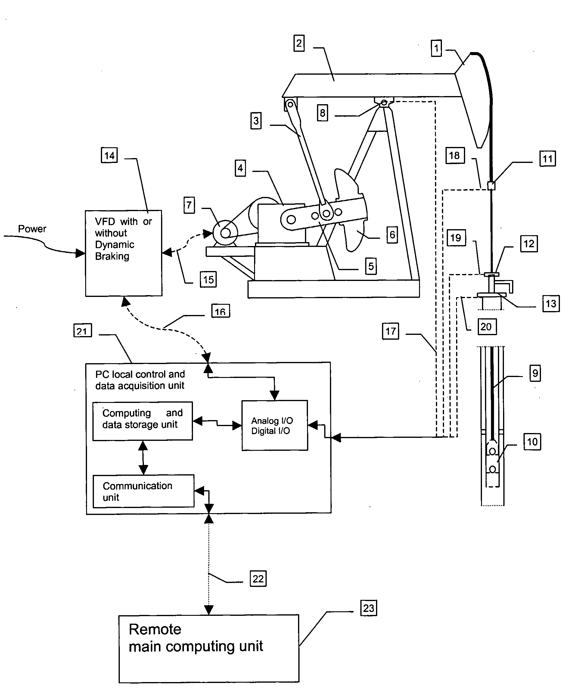
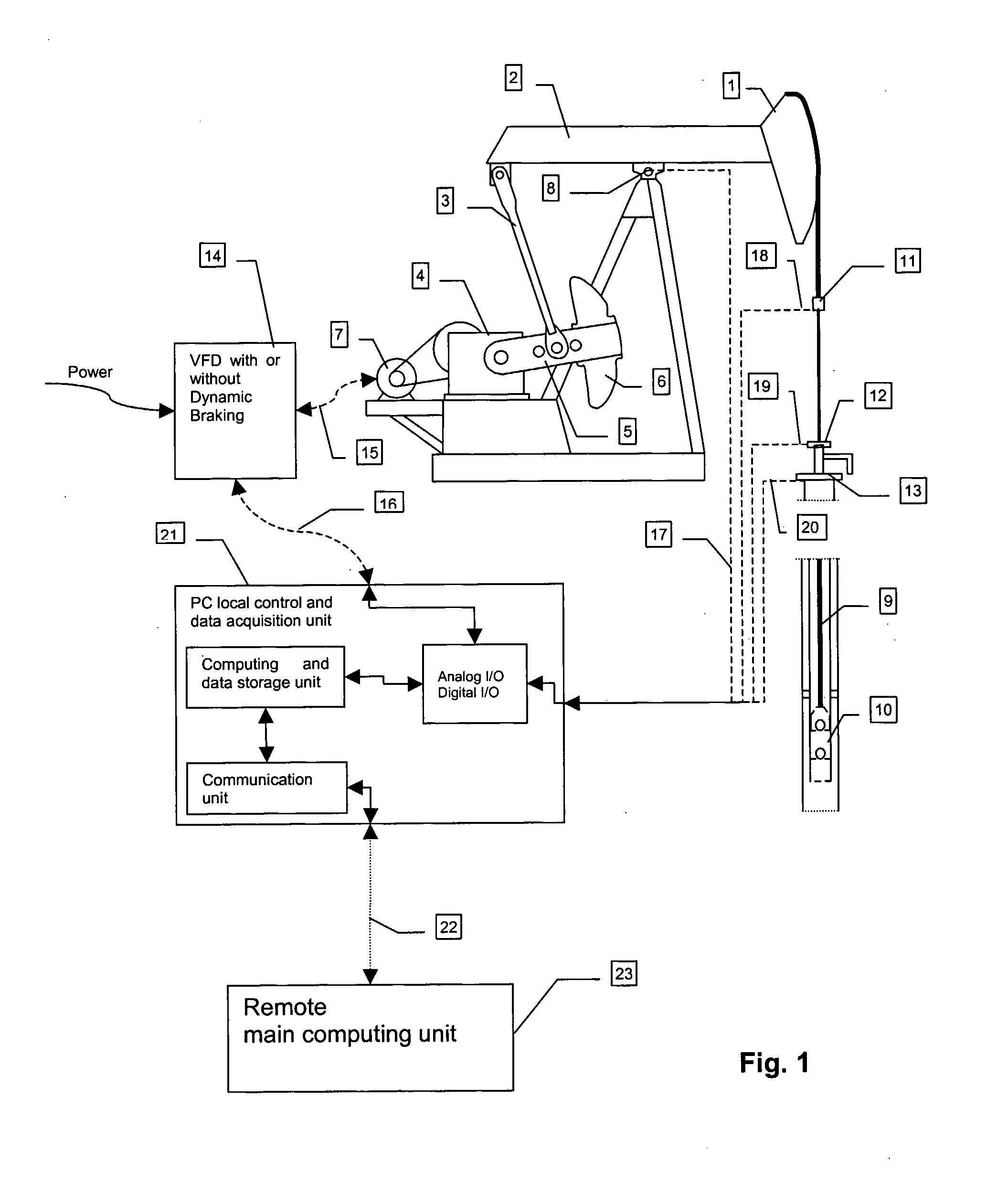
Image

Examples
Embodiment Construction
Optimization Method
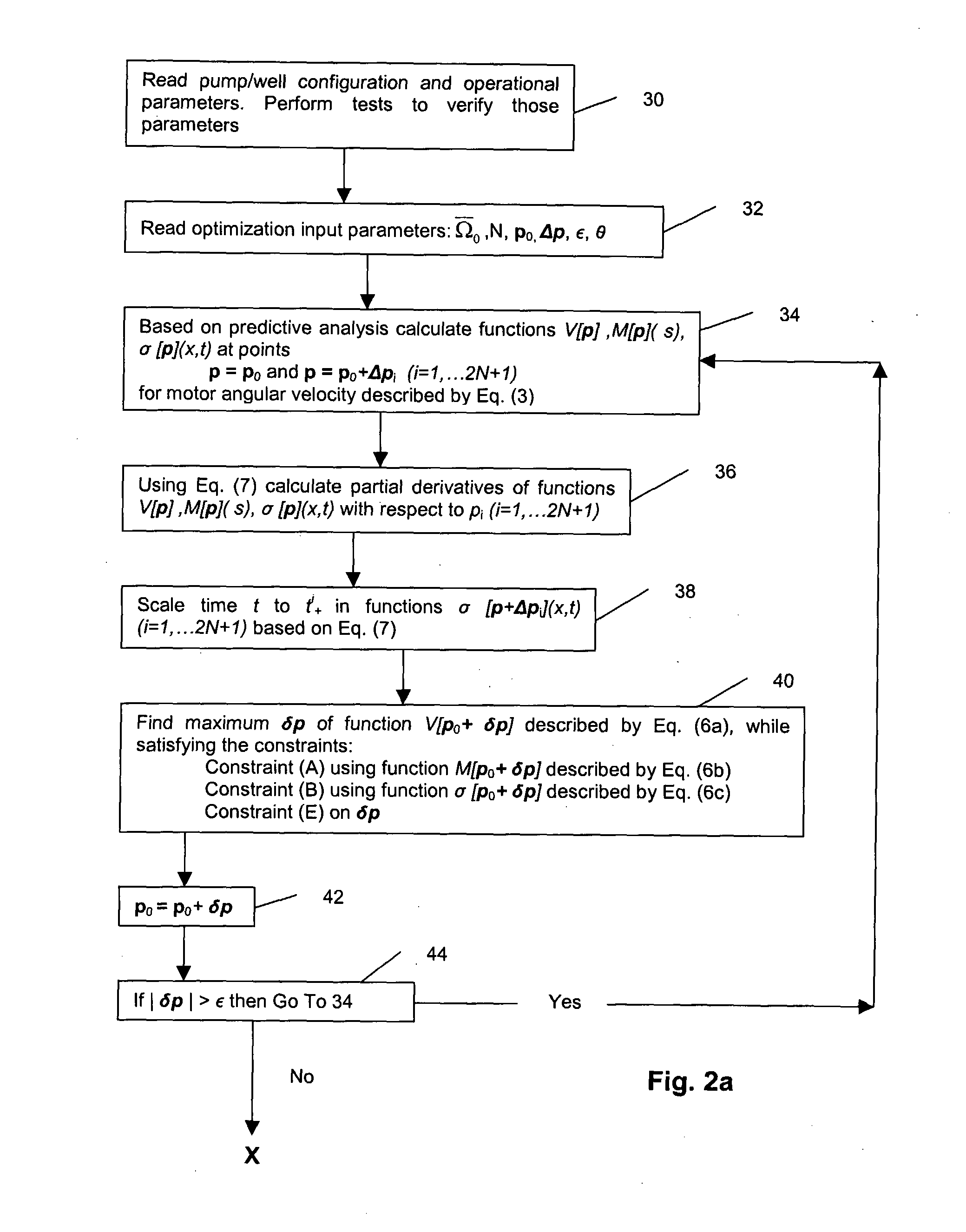
[0065]Referring now to the summary of the present invention set out above. the optimization problem (I) is defined as finding the VFD input angular speed profile Ω(s) that maximizes the average fluid volume pumped per unit time. The volume pumped during one stroke as a result of the imposed VFD input speed Ω(s) is equal to:
where[0066]Ap—plunger cross-sectional area[0067]η—pumping efficiency coefficient[0068]UP(Ω)—plunger stroke length (the product ηUP is called an effective stroke length).
[0069]Therefore. the optimization goal of maximizing the production per unit time can be mathematically defined as finding the VFD input speed profile Ω(s) that maximizes the following functional V(Ω), while satisfying the constraints (A-C):
V(Ω)=Vol(Ω)T(Ω)=ApηUP(Ω)T(Ω)=Maximum(Ω)(1)[0070]where T(Ω) is the stroke period resulting from applying the input velocity Ω(s).
[0071]Similarly, the optimization problem (II) can be defined as finding the VFD input speed profile Ω(s) that mini...
PUM
 Abstract
Description
Claims
Application Information