Downhole deployment valves

Active Publication Date: 2008-10-09
WEATHERFORD TECH HLDG LLC
View PDF10 Cites 84 Cited by
  • Summary
  • Abstract
  • Description
  • Claims
  • Application Information

AI Technical Summary

Benefits of technology

[0009]The invention generally relates to methods and apparatus that enable reliable and improved isolation between two portions of a bore extending through a casing string disposed in a borehole. A downhole deployment valve (DDV) may provide the isolation utilizing a valve member such as a flapper that is disposed in a housing of the DDV an

Problems solved by technology

Disadvantages of operating in the overbalanced condition include expense of the mud and damage to formations if the column of mud leaks off into the formations.
Since underbalanced well conditions can cause a blow out, underbalanced wells must be drilled through some type of pressure device such as a rotating drilling head at the surface of the well.
However, p

Method used


Image

  • Downhole deployment valves
  • Downhole deployment valves
  • Downhole deployment valves

Examples


Embodiment Construction

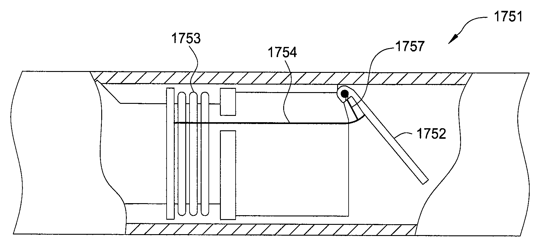
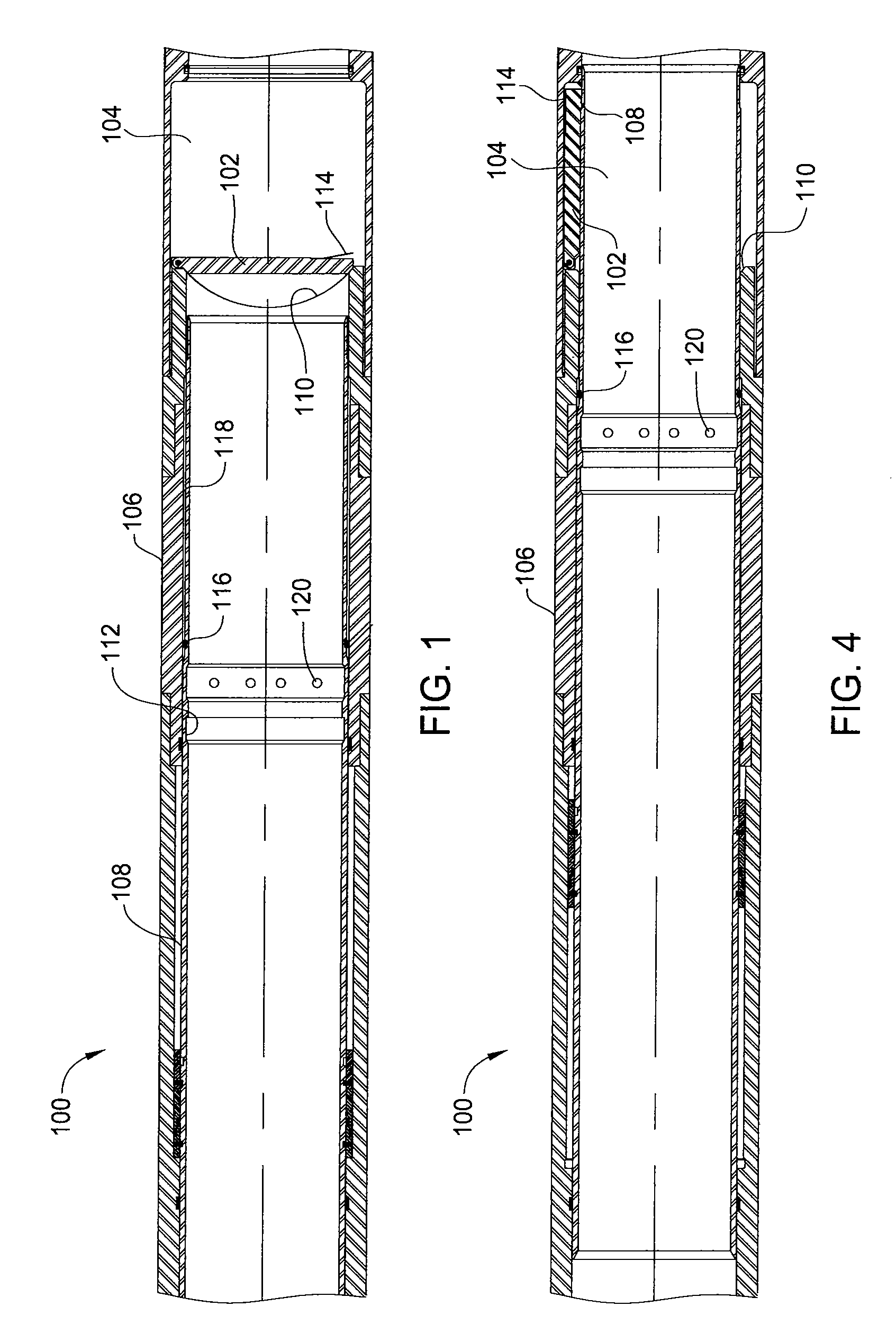
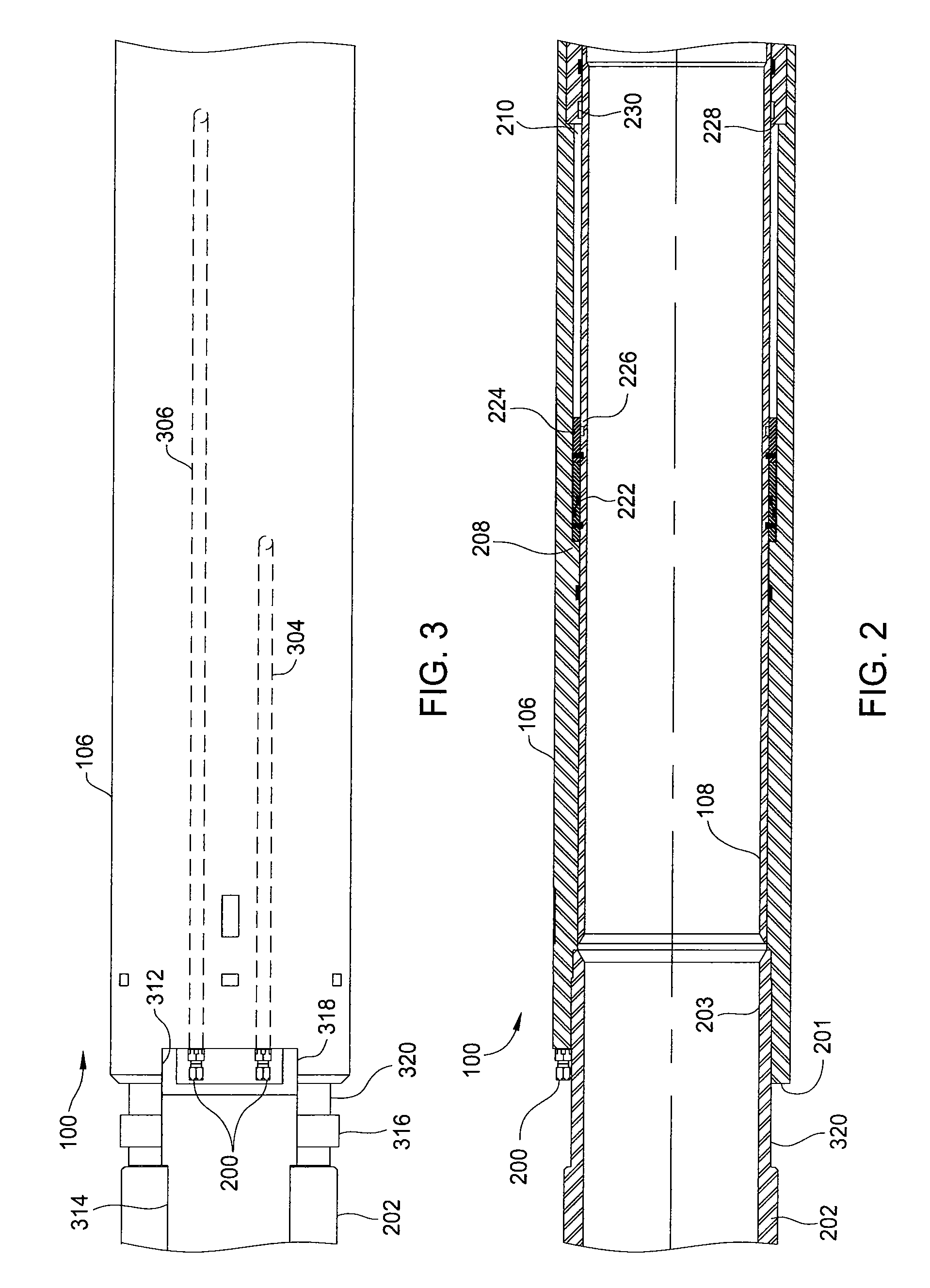
[0033]Embodiments of the invention generally relate to isolating an interior first section of a casing string from an interior second section of the casing string. The casing string may include a downhole deployment valve (DDV) that has an outer housing. In any of the embodiments described herein, the housing may form an intermediate portion of the casing string with cement disposed in an annular area between a borehole wall and an exterior surface of the casing string including an outside of the housing, depending on level of the cement in the annular area, to secure the casing string in the borehole. Further, the DDV may in any embodiment couple with a tie-back end, such as a polished bore receptacle, of a casing or liner that integrates with the DDV to form the casing string. A valve member such as a flapper valve within the DDV enables sealing between the first and second sections of the casing string such that pressure in the first section that is in fluid communication with a ...


PUM


Abstract

Methods and apparatus enable reliable and improved isolation between two portions of a bore extending through a casing string disposed in a borehole. A downhole deployment valve (DDV) may provide the isolation utilizing a valve member such as a flapper that is disposed in a housing of the DDV and is designed to close against a seat within the housing. The DDV includes an operating mechanism for opening/closing the DDV. In use, pressure in one portion of a well that is in fluid communication with a well surface may be bled off and open at well surface while maintaining pressure in another portion of the casing string beyond the DDV.

Description

CROSS-REFERENCE TO RELATED APPLICATIONS[0001]This application claims benefit of U.S. provisional patent application Ser. No. 60 / 910,129, filed Apr. 4, 2007, which is herein incorporated by reference.BACKGROUND OF THE INVENTION[0002]1. Field of the Invention[0003]Embodiments of the invention generally relate to methods and apparatus for use in oil and gas wellbores. More particularly, the invention relates to methods and apparatus for utilizing deployment valves in wellbores.[0004]2. Description of the Related Art[0005]Forming an oil / gas well begins by drilling a borehole in the earth to some predetermined depth adjacent a hydrocarbon bearing formation. After the borehole is drilled to a certain depth, steel tubing or casing inserted in the borehole forms a wellbore having an annular area between the tubing and the earth that is filled with cement. The tubing strengthens the borehole while the cement helps to isolate areas of the wellbore during hydrocarbon production.[0006]A well dr...

Claims


Application Information

Patent Timeline
IPC IPC(8): E21B34/06
CPCE21B21/08E21B2034/005E21B34/14E21B21/10Y10T137/7898E21B2200/05
Inventor NOSKE, JOEIBLINGS, DAVIDPAVEL, DAVIDBRUNNERT, DAVID J.SMITH, PAULGRAYSON, MICHAEL BRIAN
Owner WEATHERFORD TECH HLDG LLC
Why Eureka
Try Eureka