
Apparatus and method of drilling with casing

Inactive Publication Date: 2005-05-31
WEATHERFORD TECH HLDG LLC
View PDF489 Cites 79 Cited by
  • Summary
  • Abstract
  • Description
  • Claims
  • Application Information

AI Technical Summary

Benefits of technology

[0011]In another aspect, a method of forming and lining a subsea wellbore is provided. The method includes disposing a run-in string with a casing string at the lower end thereof in a riser system, the casing string having a casing mandrel disposed at an upper end thereof and a drill bit disposed at a lower end thereof. The method further includes rotating the casing string while urging the casing string axially downward to a predetermined depth, whereby the casing mandrel is at a predetermined height above a casing hanger. Additionally, the method includes reducing the length of the casing string thereby seating the casing mandrel in the casing hanger.
[0012]In yet another aspect, a method of landing a casing mandrel in a casing hanger disposed in a subsea wellhead is provided. The method includes placing a casing string with the casing mandrel disposed at the upper end thereof into a riser system and drilling the casing string into the subsea wellhead to form a wellbore. The method further includes positioning the casing mandrel at a predetermined height above the casing hanger and reducing the axial length of the casing string to seat the casing mandrel in the casing hanger.

Problems solved by technology

For example, when forming a subsea wellbore, the initial length of wellbore extending downwards from the ocean floor is subject to cave in or collapse due to soft formations at the ocean floor.
Additionally, sections of a wellbore that intersect areas of high pressure can lead to damage of the wellbore between the time the wellbore is formed and when it is lined.
An area of exceptionally low pressure will drain expensive drilling fluid from the wellbore between the time it is intersected and when the wellbore is lined.
While one-pass drilling offers obvious advantages over a conventional completion operation, there are some additional problems using the technology to form a subsea well because of the sealing requirements necessary in a high-pressure environment at the ocean floor.
Additionally, in one-pass completion an obstruction may be encountered while drilling with casing, whereby the casing hanger may not be able to move axially downward far enough to land in the subsea wellhead, resulting in the inability to seal the subsea wellhead.

Method used


Image

  • Apparatus and method of drilling with casing
  • Apparatus and method of drilling with casing
  • Apparatus and method of drilling with casing

Examples


Embodiment Construction

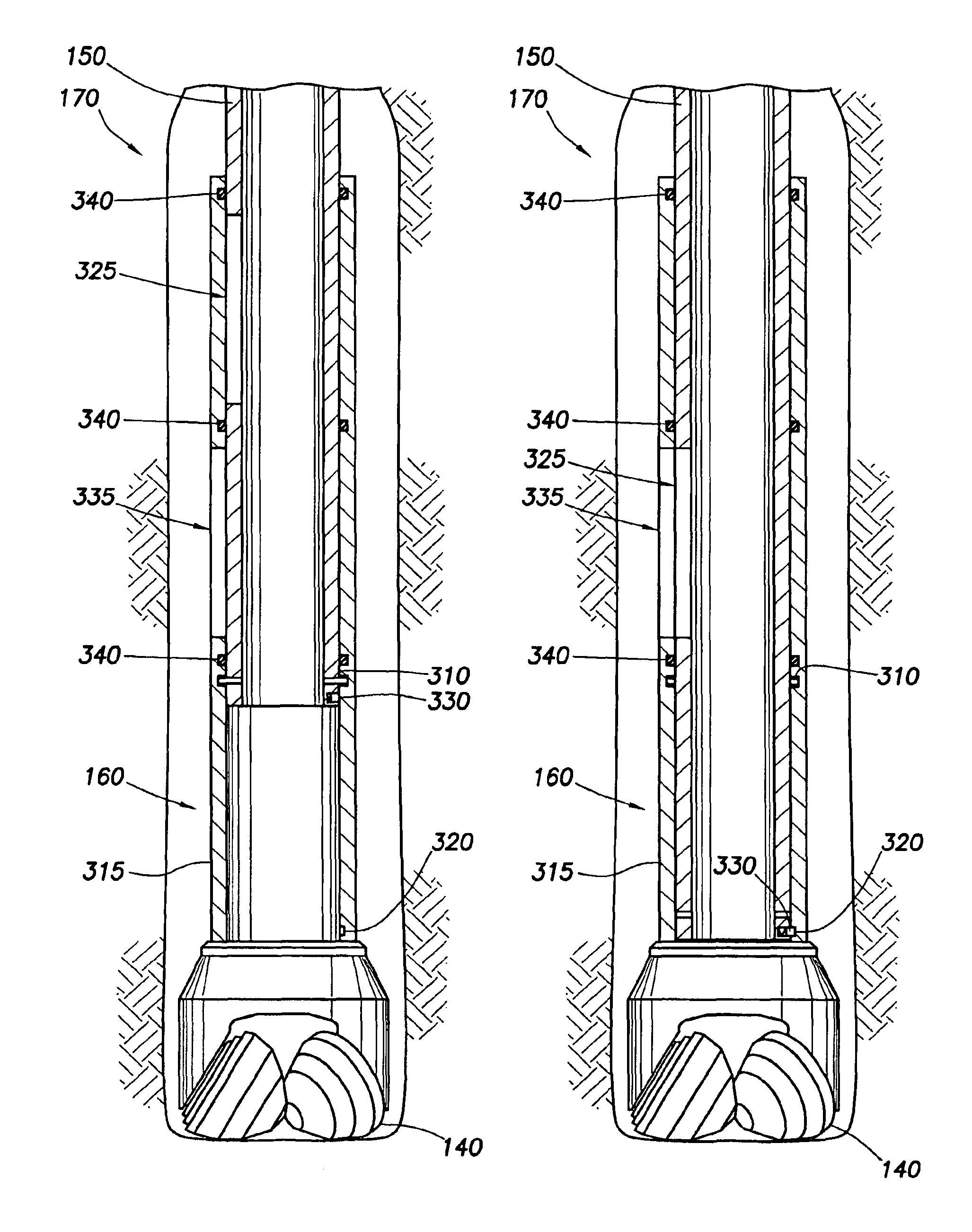
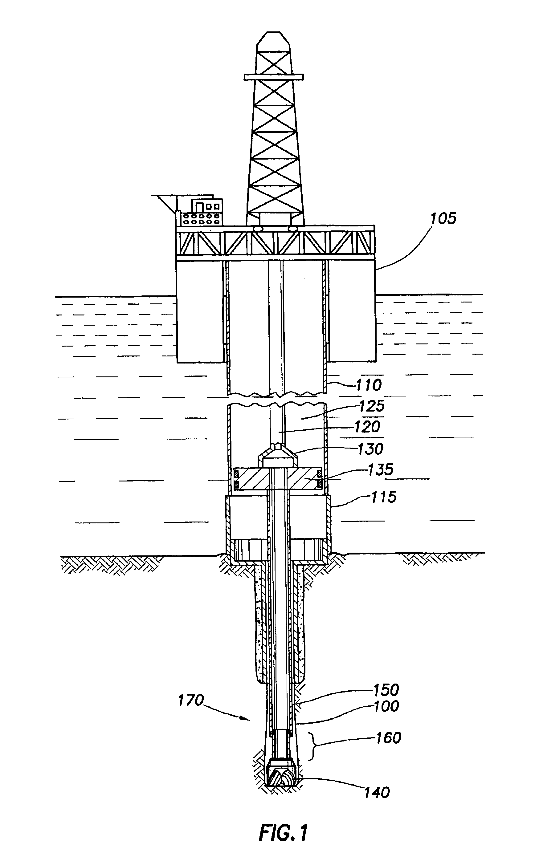
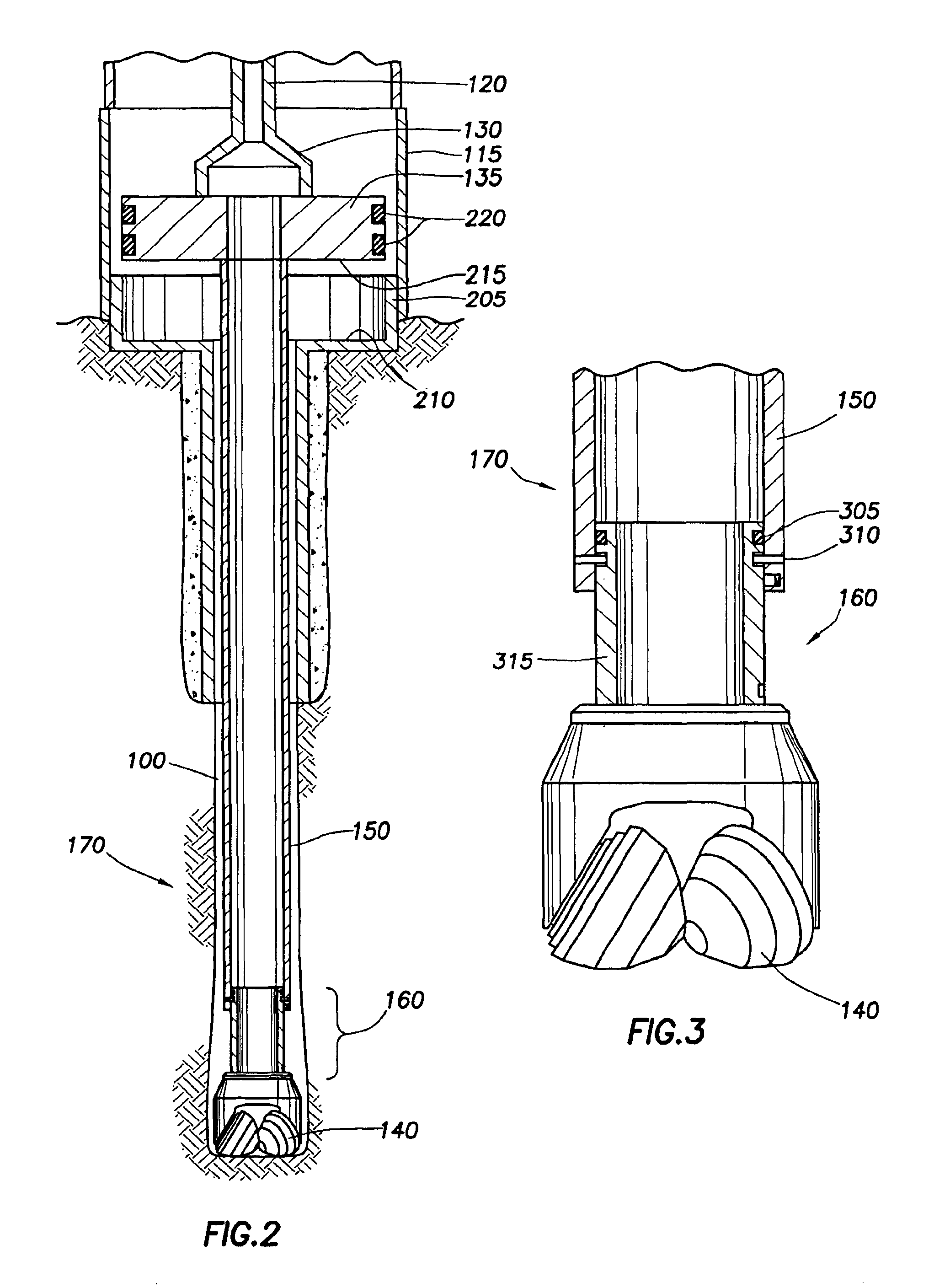
[0028]The present invention generally relates to drilling a subsea wellbore using a casing string. FIG. 1 illustrates a drilling operation of a subsea wellbore with a casing assembly 170 in accordance with the present invention. Typically, most offshore drilling in deep water is conducted from a floating vessel 105 that supports the drill rig and derrick and associated drilling equipment. A riser pipe 110 is normally used to interconnect the floating vessel 105 and a subsea wellhead 115. A run-in string 120 extends from the floating vessel 105 through the riser pipe 110. The riser pipe 110 serves to guide the run-in string 120 into the subsea wellhead 115 and to conduct returning drilling fluid back to the floating vessel 105 during the drilling operation through an annulus 125 created between the riser pipe 110 and run-in string 120. The riser pipe 110 is illustrated larger than a standard riser pipe for clarity.

[0029]A running tool 130 is disposed at the lower end of the run-in st...


PUM


Abstract

The present invention generally relates to methods for drilling a subsea wellbore and landing a casing mandrel in a subsea wellhead. In one aspect, a method of drilling a subsea wellbore with casing is provided. The method includes placing a string of casing with a drill bit at the lower end thereof in a riser system and urging the string of casing axially downward. The method further includes reducing the axial length of the string of casing to land a wellbore component in a subsea wellhead. In this manner, the wellbore is formed and lined with the string of casing in a single run. In another aspect, a method of forming and lining a subsea wellbore is provided. In yet another aspect, a method of landing a casing mandrel in a casing hanger disposed in a subsea wellhead is provided.

Description

BACKGROUND OF THE INVENTION[0001]1. Field of the Invention[0002]The present invention relates to wellbore completion. More particularly, the invention relates to methods for drilling with casing and landing a casing mandrel in a subsea wellhead.[0003]2. Description of the Related Art[0004]In a conventional completion operation, a wellbore is formed in several phases. In a first phase, the wellbore is formed using a drill bit that is urged downwardly at a lower end of a drill string while simultaneously circulating drilling mud into the wellbore. The drilling mud is circulated downhole to carry rock chips to the surface and to cool and clean the bit. After drilling a predetermined depth, the drill string and bit are removed.[0005]In a next phase, the wellbore is lined with a string of steel pipe called casing. The casing is inserted into the newly formed wellbore to provide support to the wellbore and facilitate the isolation of certain areas of the wellbore adjacent to hydrocarbon b...

Claims


Application Information

Patent Timeline
IPC IPC(8): E21B17/07E21B33/03E21B17/02E21B7/20E21B33/04E21B41/00E21B7/06E21B7/08
CPCE21B7/061E21B7/20E21B41/0035E21B33/04E21B17/07E21B17/00
Inventor GALLOWAY, GREGORY G.BRUNNERT, DAVID J.
Owner WEATHERFORD TECH HLDG LLC
Learn More