
Method and apparatus for temporarily maintaining a downhole foam element in a compressed state

Inactive Publication Date: 2005-03-17
HALLIBURTON ENERGY SERVICES INC
View PDF12 Cites 80 Cited by
  • Summary
  • Abstract
  • Description
  • Claims
  • Application Information

AI Technical Summary

Benefits of technology

The present invention provides an apparatus for temporarily maintaining a compressible tubular foam element in a compressed state against an outer surface of a downhole sand control device. The apparatus keeps the compressible tubular foam element in a compressed state so that a production assembly comprising the sand control device and compressible tubular foam element mounted on the sand control device can be placed downhole in a production zone. The compressible tubular foam element is permeable to the hydrocarbons and thus during normal operation permits production to flow radially into the production assembly. The apparatus includes a degradable wrap securely fitted around the compressible tubular foam element. The degradable wrap is biodegradable and gradually degrades by thermal hydrolysis in the presence of an aqueous solution. The compressible tubular foam element remains in the annulus formed between the production assembly and the casing string or well bore and operates to inhibit the normal flow of water along the annulus. The method includes the steps of installing a production assembly downhole within the well bore, installing an isolation pipe in a blank section of the production assembly, and sealing the top and bottom ends of the isolation pipe to the production assembly. The technical effects of the invention include maintaining the compressible tubular foam element in a compressed state, preventing water from entering a particular zone, and inhibiting the normal flow of water along the annulus.

Problems solved by technology

Once the production assembly is in place adjacent to the production zone, the degradable wrap degrades, thereby causing the compressible tubular foam element to expand filling the annulus formed between the production assembly and the casing string or well bore.

Method used


Image

  • Method and apparatus for temporarily maintaining a downhole foam element in a compressed state
  • Method and apparatus for temporarily maintaining a downhole foam element in a compressed state
  • Method and apparatus for temporarily maintaining a downhole foam element in a compressed state

Examples


Embodiment Construction

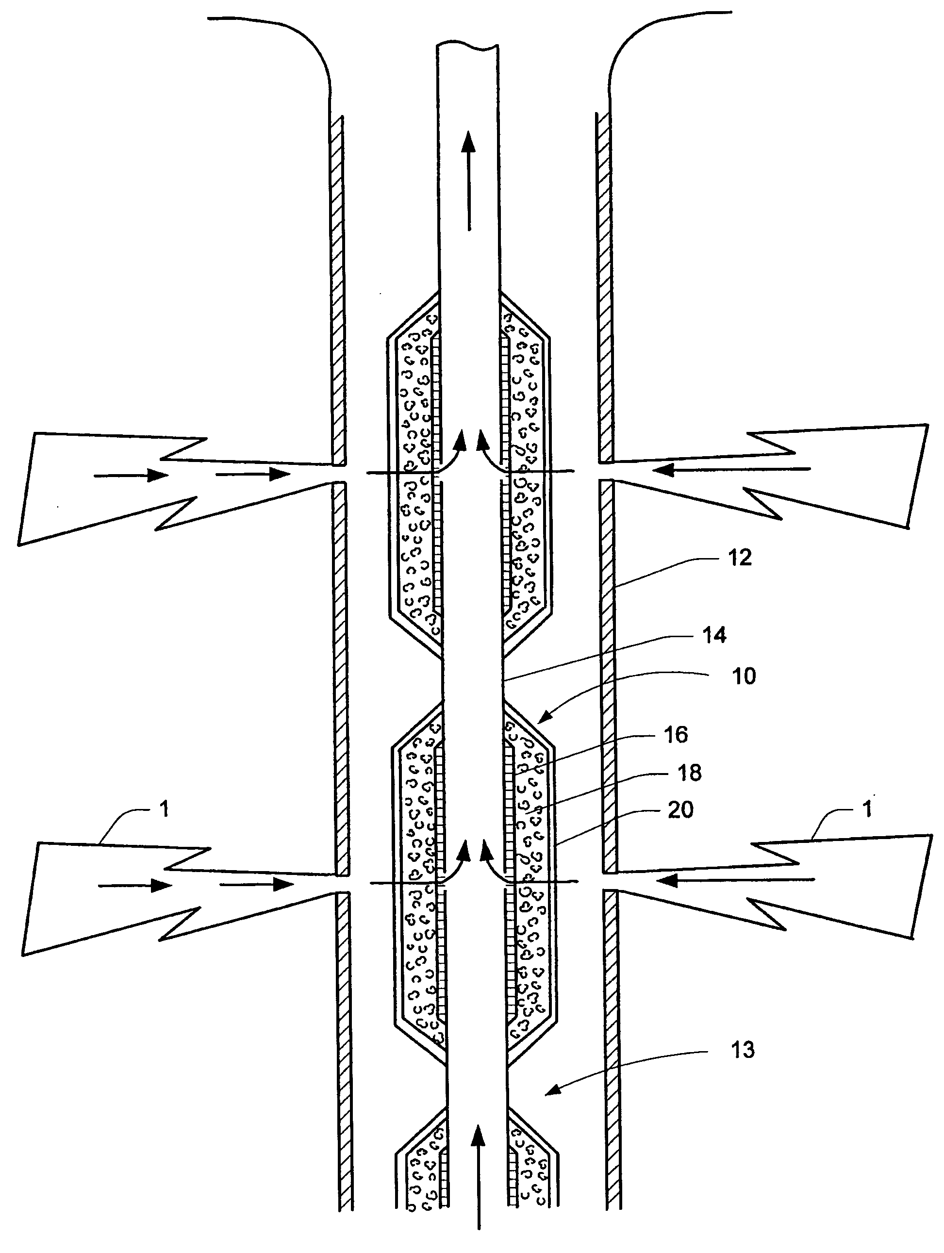
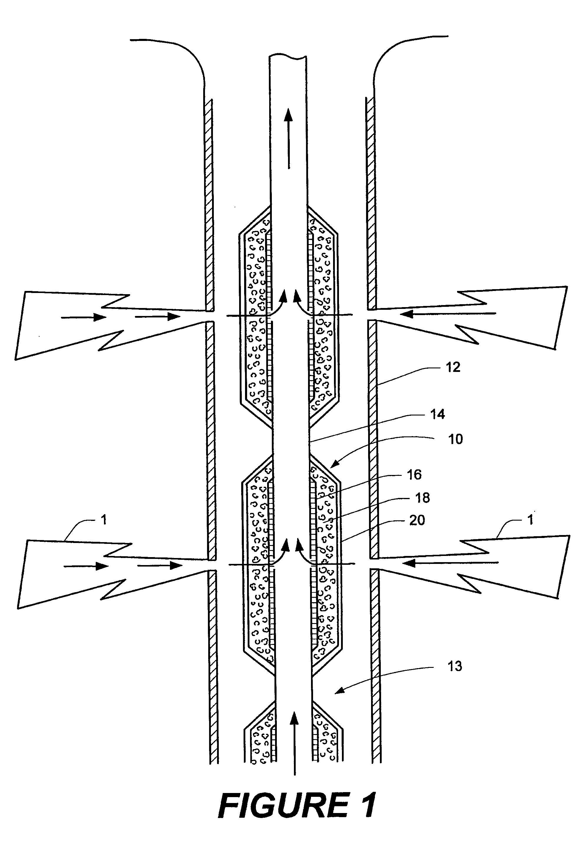
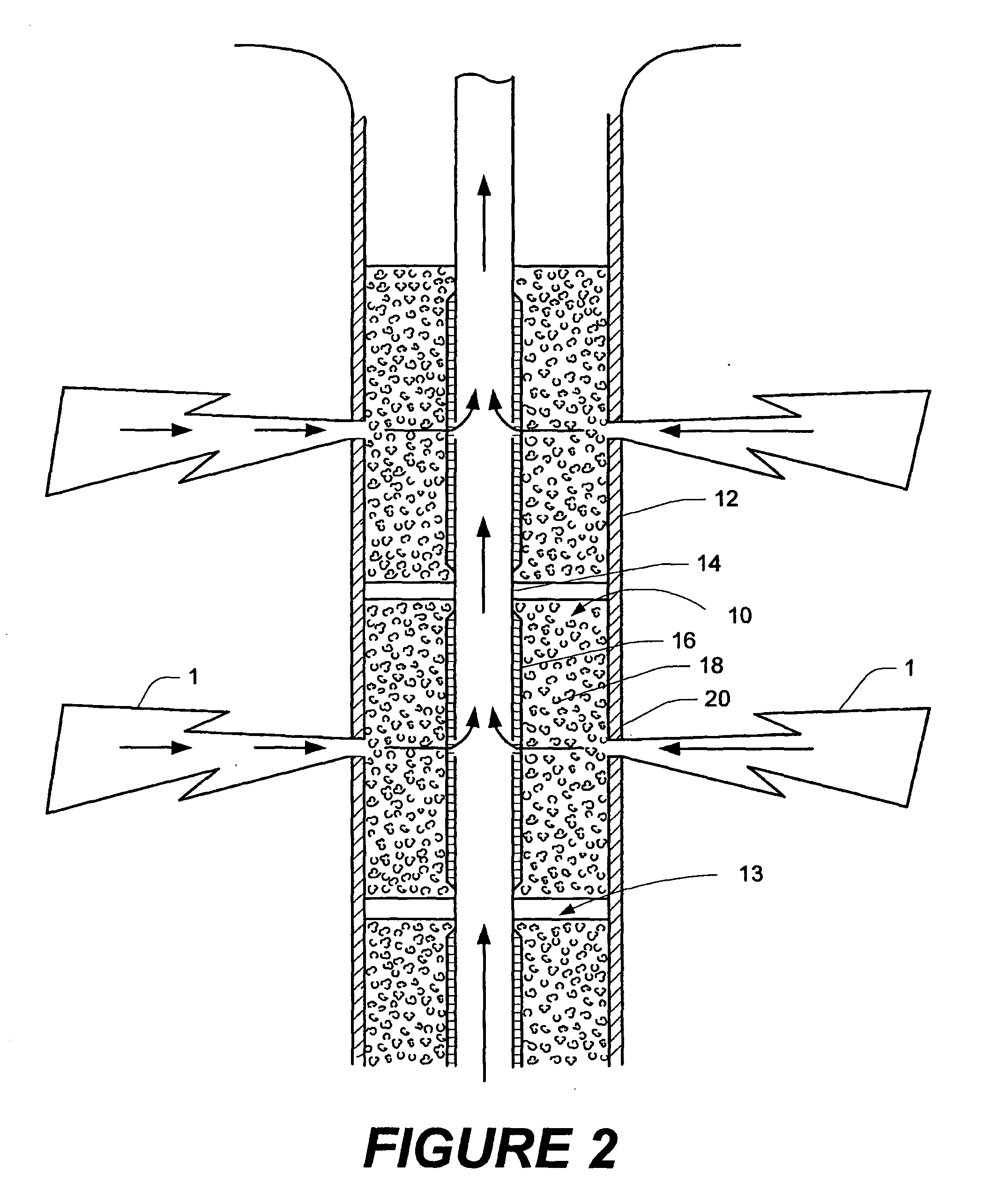
The details of the present invention will now be discussed with reference to the figures. Turning to FIG. 1, a multi-sectional production assembly in accordance with the present invention is shown generally by reference numeral 10. The production assembly 10 is shown disposed downhole inside of a casing string 12, which in turn is cemented to the wall of the well bore. The casing string 12 is perforated in the production zone, which is referred to generally by reference numeral 1. As those of ordinary skill in the art will recognize, the present invention has application in open holes as well as those lined with casing string. An annulus 13 is formed between the production assembly 10 and the casing string 12.

The production assembly 10 is formed of a base pipe 14, which is preferably a steel pipe, which has a plurality of openings to allow a production fluid to flow from the production zone 1 into the base pipe 14. The production assembly 10 comprises a sand control device 16, wh...


PUM


Abstract

The present invention is directed to a degradable wrap and method for temporarily maintaining a downhole foam element in a compressed state. The degradable wrap is fitted around the foam element and temporarily maintains the foam element in a compressed state against an outer surface of a downhole sand control device. It is provided to keep the foam element in the compressed state while a production assembly comprising the downhole sand control device and foam element mounted thereon is placed downhole in a well bore adjacent to a production zone. The degradable wrap is permeable to the production fluid and degrades over time. Once the degradable wrap has degraded the foam element fills the annulus between the production screen and casing string or well bore wall. The foam element acts to inhibit the flow of water along the annulus and is useful in zone isolation.

Description

BACKGROUND OF THE INVENTION The present invention relates generally to methods and apparatuses for controlling fluid flow in a downhole annulus, and more particularly to a method and apparatus for temporarily maintaining a downhole foam element in a compressed state until it needs to expand and fill the annulus to thereby inhibit fluid flow therein. Very often during recovery of hydrocarbons from a subterranean formation water is produced along with the hydrocarbons. This is undesirable because it necessitates having to remove the water from the production fluid, which is typically expensive. It also creates the problem of having to dispose of the contaminated water, which is particularly problematic in offshore applications. To alleviate the problem, techniques have been developed to isolate regions of the production zone where the water enters the well. These techniques are commonly known as zone isolation. Zone isolation is generally accomplished in long, extended or horizontal...

Claims


Application Information

Patent Timeline
Patent Type & Authority Applications(United States)
IPC IPC(8): E21B33/12E21B43/12
CPCE21B43/12E21B33/1208
Inventor GRIGSBY, TOMMY F.PROCYK, ALEXANDER D.TODD, BRADLEY L.
Owner HALLIBURTON ENERGY SERVICES INC
Learn More