Locking System for Windows and Doors

a technology for windows and doors and locking systems, applied in the direction of mechanical devices, wing accessories, carpet fasteners, etc., can solve the problems of difficult to lock the problem of difficult to hold the entire side edge of the sash against the frame for locking purposes, so as to improve the locking assembly

Inactive Publication Date: 2008-10-16
ROTO FRANK OF AMERICA
View PDF24 Cites 22 Cited by
  • Summary
  • Abstract
  • Description
  • Claims
  • Application Information

AI Technical Summary

Benefits of technology

[0009]In satisfaction of the aforenoted needs, improved lock asse

Problems solved by technology

In the past, the locking of a casement window sash to a window frame has been problematic because casement window sashes have a tendency to warp with age and therefore it can be difficult to hold an entire side edge of a sash against a frame for locking purposes.
Further, casement window operators typically apply the closing force to only one end of the casement window sash, e.g., the bottom end, and therefore there is a tendency for one end of the sash to engage the frame before the opposing end of the sa

Method used


Image

  • Locking System for Windows and Doors
  • Locking System for Windows and Doors
  • Locking System for Windows and Doors

Examples


Embodiment Construction

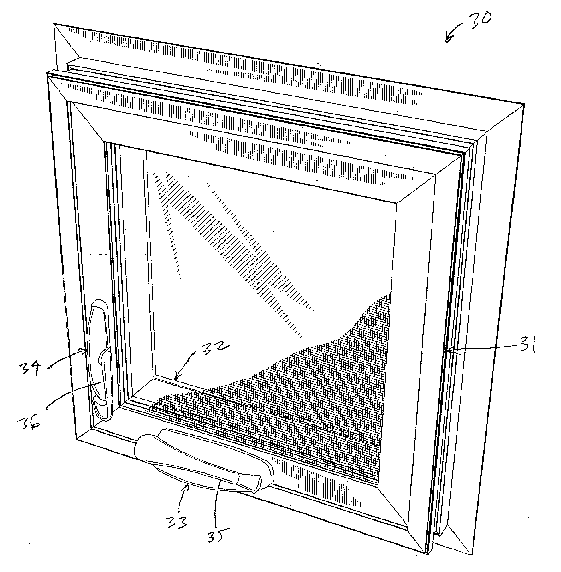
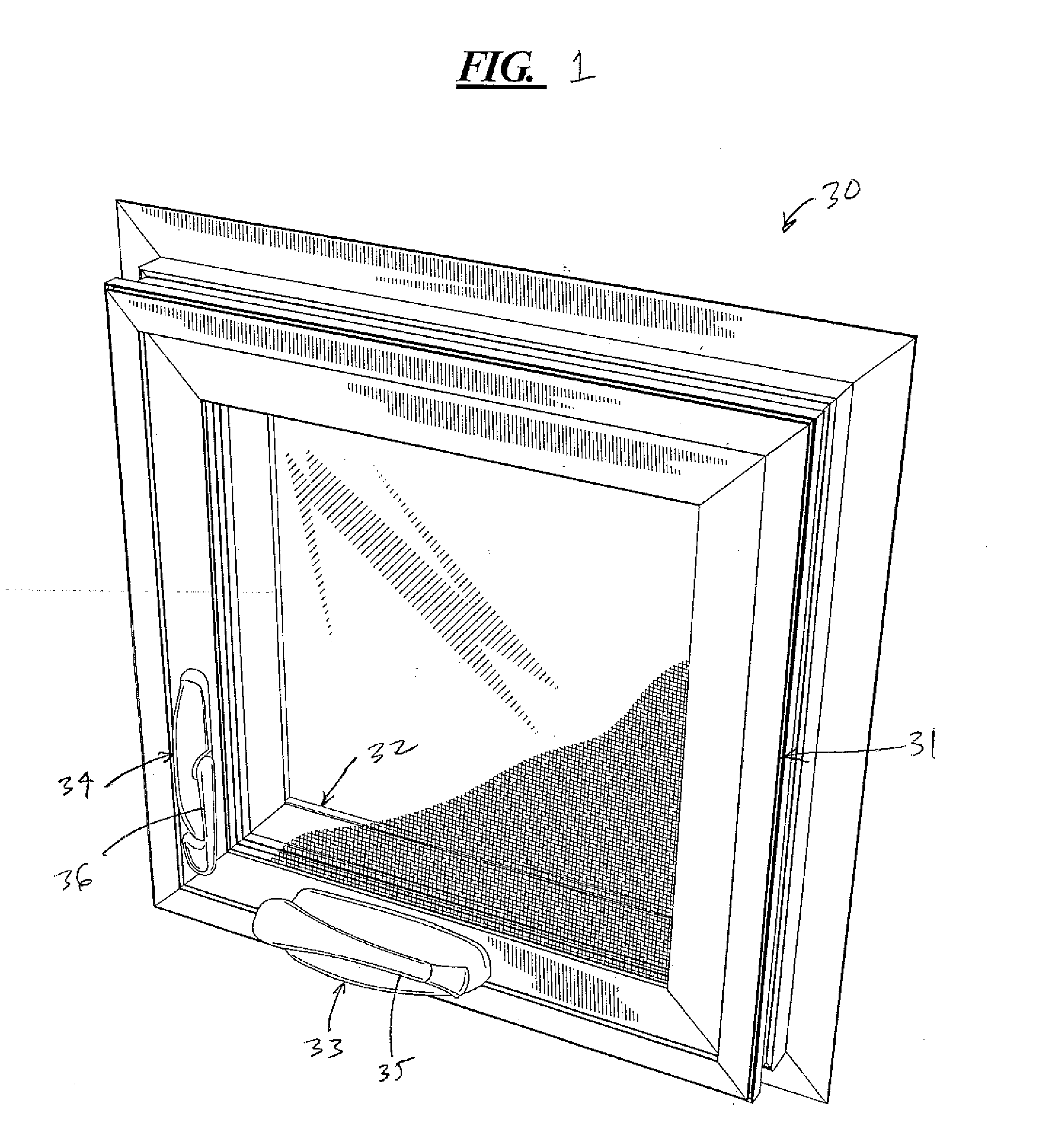
[0058]Turning first to FIG. 1, a casement window 30 is shown that is of the type for which the disclosed locking systems are intended. The window 30 includes a stationary window frame 31 and a pivoting window sash 32. Also shown in FIG. 1 is a crank operator 33 and a lock actuator 34. Both the crank operator 33 and lock actuator 34 include handles 35, 36 respectively. The window 30 of FIG. 1 is a vinyl window, although the lock systems are disclosed herein can be used on either vinyl or wood windows

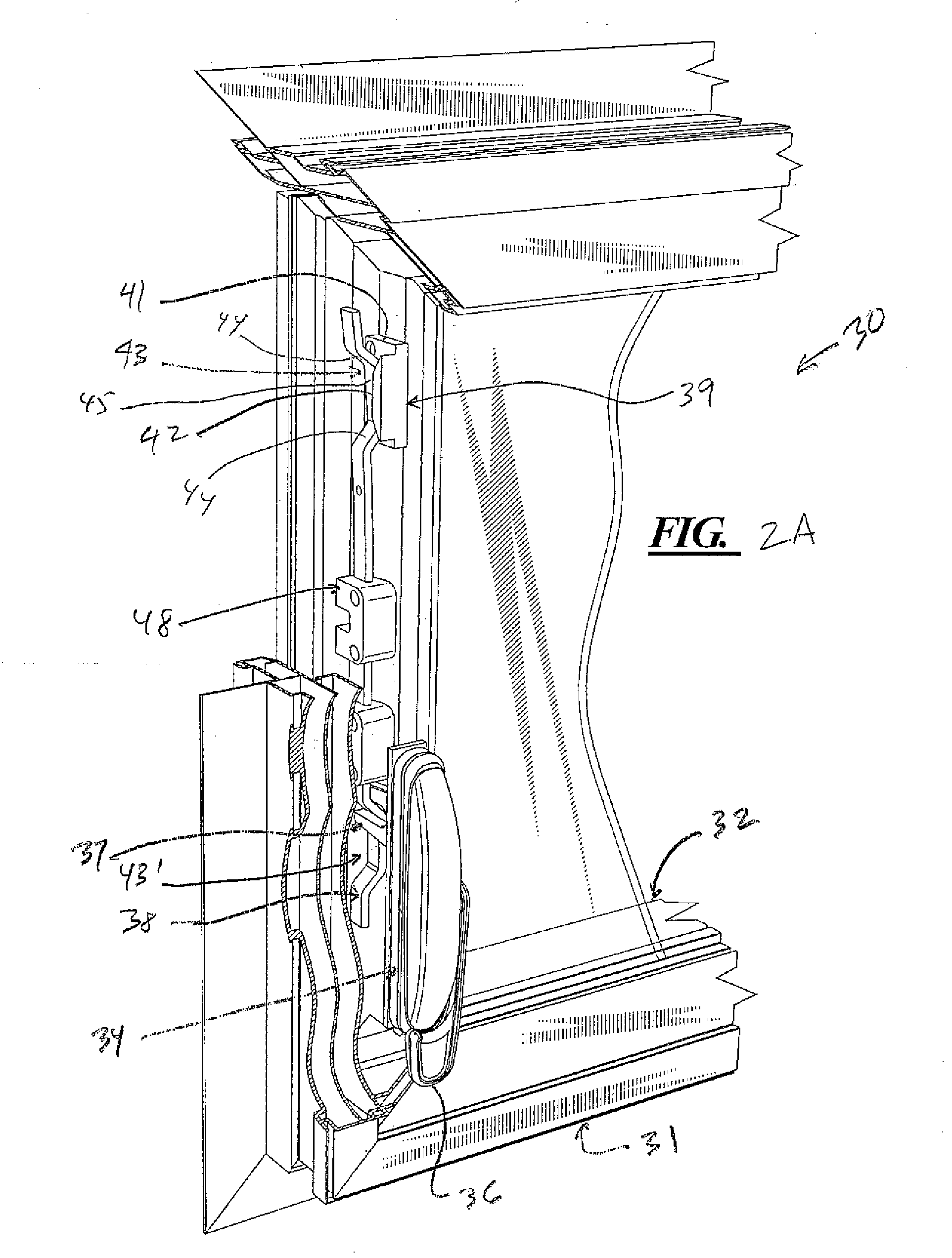
[0059]Turning to FIG. 2B, a partial view of the window 30 is shown with the window 30 in a closed position. The lock actuator 34 comprises a fork 37 that is coupled to a tie bar 38. The fork 37 is also coupled to the handle 36, the details of which ale not shown and not important to the present application, which is directed toward the tie bar 38, striker 39 and variations thereof. While the coupling mechanism between the lock actuator 34 and the tie bar 38 is shown as a fork 37, other co...


PUM


Abstract

A lock system for casement windows is disclosed which includes a tie bar slidably secured to the flame. The tie bat is secured to a lock handle that is also secured to the flame. The tie bat eliminates the need for rollers riveted to the tie bar by having a first bent section disposed between straight sections and a second bent section disposed between straight sections. All of the straight sections are linearly aligned with one another and at least some of the straight sections of the tie bar are slidably mounted to the flame using conventional guides. The lock system also includes first and second strikers mounted to the sash. The first striker comprising a first ramp that receives a first bent section and the second striker comprising a second ramp that receives a second bent section when the tie bat is slidably moved towards the first and second strikers as the tie bar is moved from an unlocked position to a locked position. Movement of the first and second bent sections along the first and second ramps respectively as the tie bar moves towards the locked position results in the sash and frame being pulled together. A third bent section may be included towards the middle of the tie bar and used to couple the tie bar to the lock handle or actuator.

Description

BACKGROUND[0001]1. Technical Field[0002]A locking system for windows and doors is disclosed which includes an otherwise straight tie bar with one or more bent sections therein for engaging strikers fixedly mounted to the window sash or door. An additional bent section may be provided near or at the middle of the bar for purposes of coupling the bar to a lock handle. Adjustable strikers are also disclosed that may be used with the disclosed tie bars.[0003]2. Description of the Related Art[0004]Casement windows are known. In the past, the locking of a casement window sash to a window frame has been problematic because casement window sashes have a tendency to warp with age and therefore it can be difficult to hold an entire side edge of a sash against a frame for locking purposes. Further, casement window operators typically apply the closing force to only one end of the casement window sash, e.g., the bottom end, and therefore there is a tendency for one end of the sash to engage the...

Claims


Application Information

Patent Timeline
IPC IPC(8): E05F11/24
CPCE05B15/0245E05B15/025E05C9/02E05C9/1808E05C9/22Y10S292/20Y10T292/0844Y10T292/0967
Inventor GRIFFIN, CHRISTOPHER PAULNORRIS, JEFFREY QUINNLEE, NATHANAEL THOMAS
Owner ROTO FRANK OF AMERICA
Why Eureka
Try Eureka