Touch Screen System with Hover and Click Input Methods

a touch screen and input method technology, applied in the field of touch screen sensitive screens, can solve the problems of inability to provide separate tracking or dragging operations, difficulty in precise touch screen interactions, and lack of sensing precision, and achieve the effect of small touch area and larger touch area

Inactive Publication Date: 2008-10-23
SMART TECH INC (CA)
View PDF101 Cites 283 Cited by
  • Summary
  • Abstract
  • Description
  • Claims
  • Application Information

AI Technical Summary

Benefits of technology

[0014]The object interacting with the touch screen may be a finger, stylus or other object capable of producing a first touch area and a relatively larger second touch area. For example, the object may comprise a stylus having a spring loaded plunger protruding from a tip of the stylus, where the plunger produces a relatively small touch area when interacting with the touch sc

Problems solved by technology

With all such technologies, the size of human fingers and the lack of sensing precision can make precise touch screen interactions difficult.
However, most conventional touch screen systems register a selection (i.e., a “click”) only when contact between the user's finger or stylus and the touch screen surface is either established or broken, and thus do not provide for separate tracking or dragging operations.
All of these technologies require the ability to directly sense the pressure or area of a touch (i.e., the surface area of the touch screen contacted by a finger or stylus) and thus are not applicable in touch screen systems that lack such ability, including infrared touch screen systems and optical touch screen s

Method used


Image

  • Touch Screen System with Hover and Click Input Methods
  • Touch Screen System with Hover and Click Input Methods
  • Touch Screen System with Hover and Click Input Methods

Examples


Embodiment Construction

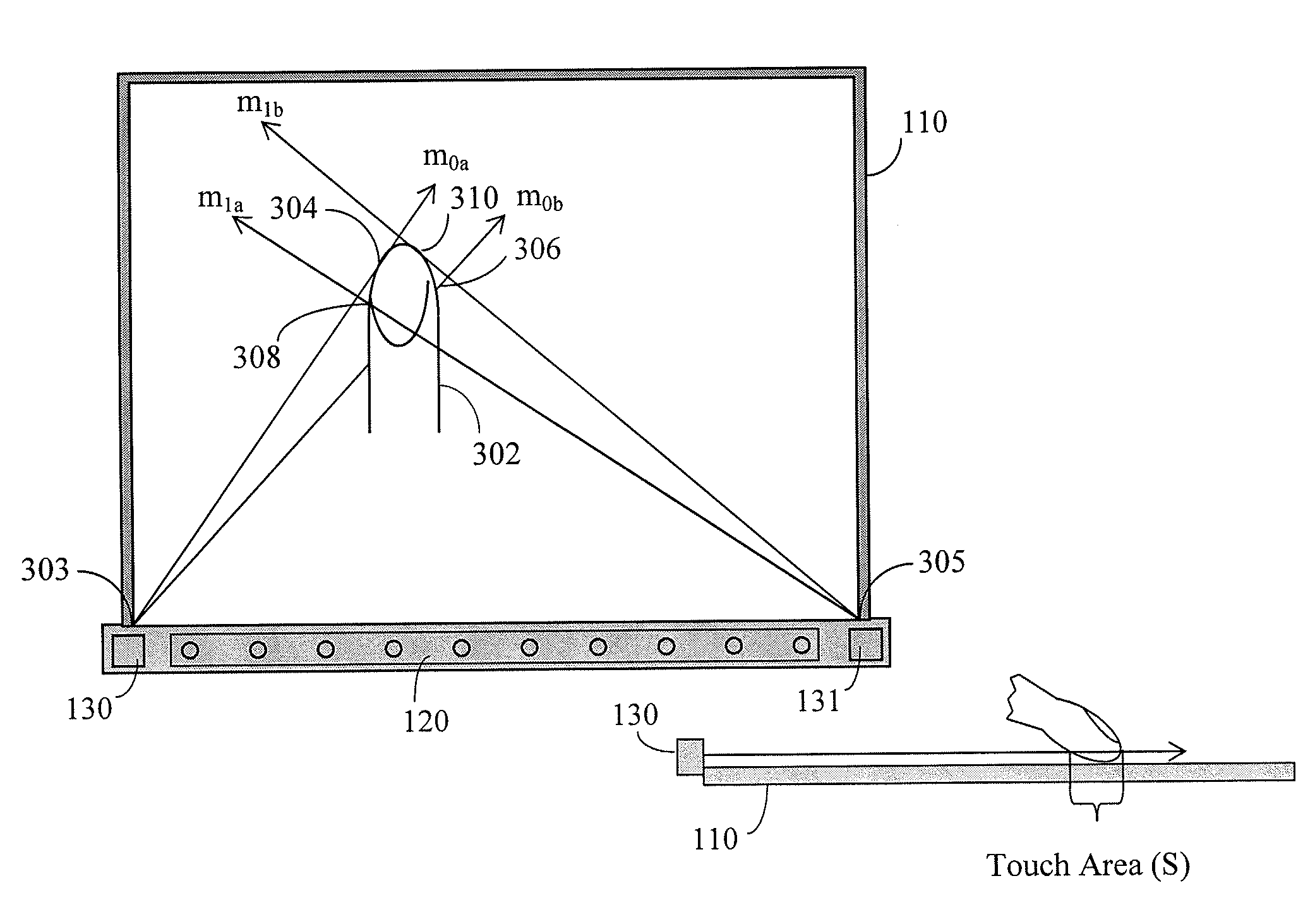
[0023]The present invention provides touch screen systems and methods for approximating at least four interaction states: (1) out-of-range; (2) tracking; (3) selection; and (4) dragging. The systems and methods of the present invention provide functionality for discerning between the various interaction states regardless of the orientation of the user's finger, stylus or other touch object and without reliance on direct sensing of touch pressure or area. Exemplary embodiments of the present invention will hereinafter be described with reference to the drawings, in which like reference numerals represent like elements throughout the several figures.

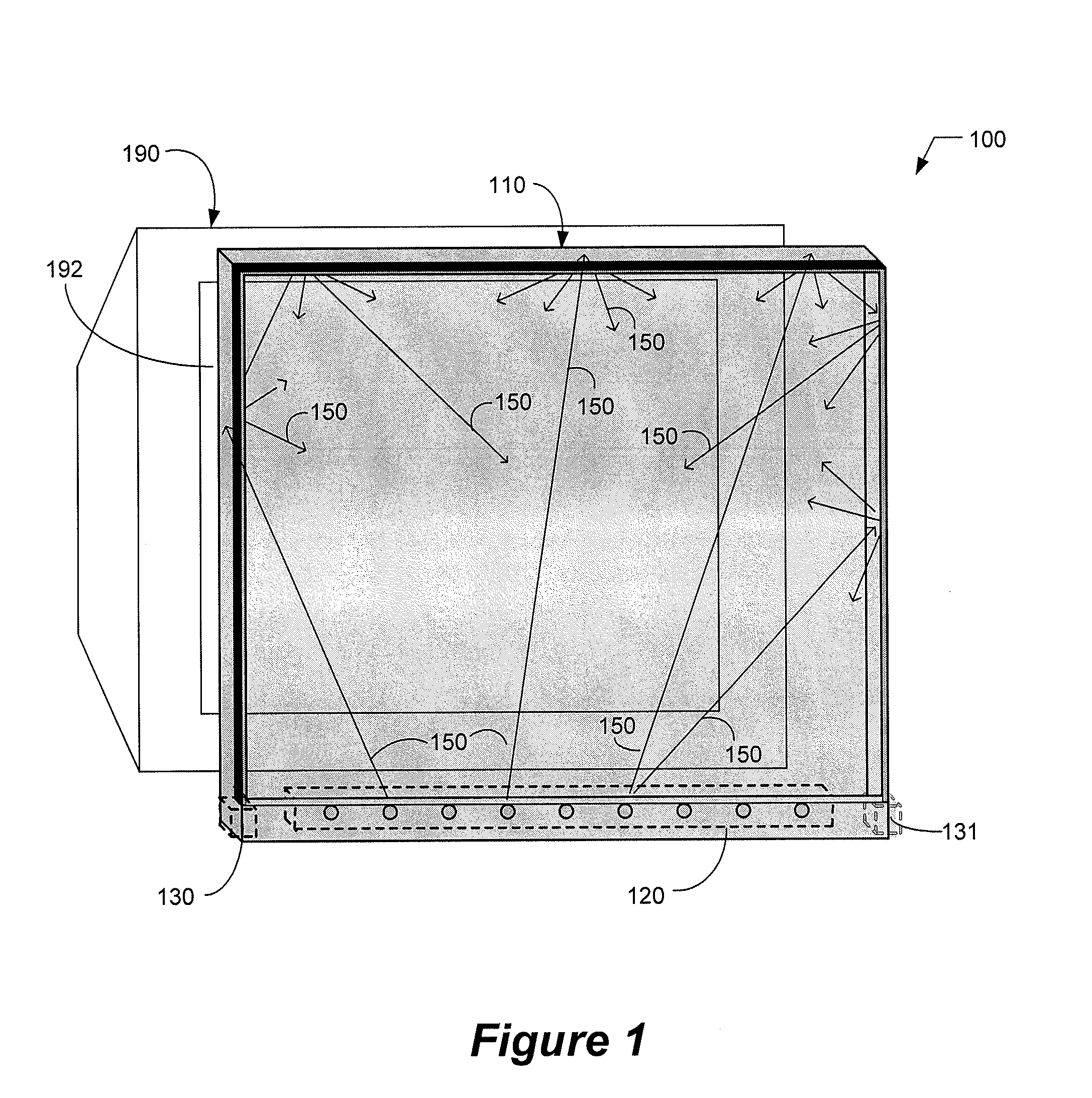
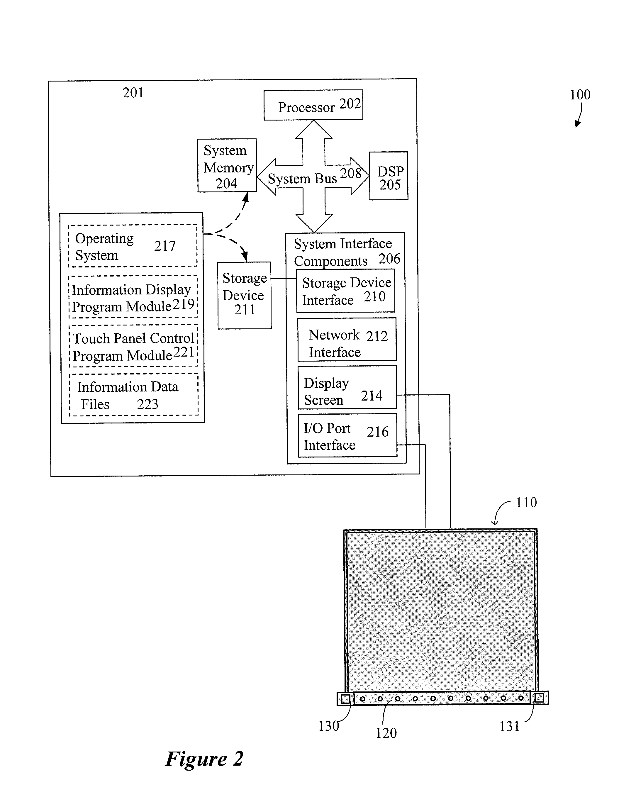
[0024]FIG. 1 is an illustration of an exemplary touch screen system 100. As used herein, the term “touch screen system” is meant to refer to a touch screen 110 and the hardware and / or software components that provide touch detection functionality. The exemplary touch screen system 100 is shown adjacent to a display device (i.e., video moni...


PUM


Abstract

A touch screen system that can approximate tracking and dragging states regardless of the user's orientation and without reliance on direct sensing of touch pressure or area. A first detector generates a signal representing a first image of an object interacting with the touch screen. A second detector generates a signal representing a second image of the object. A signal processor processes the first signal to determine approximated coordinates of a first pair of outer edges of the object and processes the second signal to determine approximated coordinates of a second pair of outer edges of the object. The signal processor then calculates an approximated touch area based on the approximated coordinates of the first pair of outer edges and the approximated coordinates of the second pair of outer edges of the object. If the approximated touch area is less than or equal to a threshold touch area, the signal processor determines that the object interacting with the touch screen indicates a tracking state. If the approximated touch area is greater than the threshold touch area, the signal processor determines that the object interacting with the touch screen indicates a selection state. The threshold touch area may be established by calibrating the touch screen system when the object interacting with the touch screen is known to indicate the tracking state.

Description

RELATED APPLICATIONS[0001]This application claims priority to New Zealand Provisional Patent Application No. 554,416, entitled “Touch Screen with Hover and Click Input Methods,” which was filed in the New Zealand Patent Office on Apr. 11, 2007.TECHNICAL FIELD[0002]The present invention relates generally to touch sensitive screens, also referred to as touch screens. More particularly, the present invention relates to systems and methods for using signal processing to optically detect user interactions with a touch screen representing tracking, selecting and dragging operations.BACKGROUND OF THE INVENTION[0003]Touch screen systems of the prior art can be categorized into the following technology groups: resistive, surface capacitive, projected capacitive, surface acoustic wave (SAW), infrared (IR), Frustrated Total Internal Reflection (FTIR), optical, and dispersive signal (bending wave). Each type of touch screen technology has its own features, advantages and disadvantages. With all...

Claims


Application Information

Patent Timeline
IPC IPC(8): G06F3/042
CPCG06F3/0421
Inventor NEWTON, JOHN
Owner SMART TECH INC (CA)
Why Eureka
Try Eureka