Apparatus and method for detecting optical systems in a terrain

a technology of optical systems and apparatus, applied in the field of military weapons, can solve the problems of inconvenient apparatus, gunner must have fired at least one projectile, and the armed forces are increasingly challenged by hostile optical systems

Inactive Publication Date: 2008-10-23
CARL ZEISS OPTRONICS
View PDF7 Cites 12 Cited by
  • Summary
  • Abstract
  • Description
  • Claims
  • Application Information

AI Technical Summary

Benefits of technology

[0015]It is, therefore, an object underlying the invention, to further improve a method and an apparatus of the type specified at the outset, such that the afore-mentioned disadvantages are avoided. In particular, a method and an apparatus shall be provided, which, by means of

Problems solved by technology

In the course of military conflicts, armed forces are increasingly challenged by hostile optical systems, in particular during non-conventional warfare which happens more and more often.
This prior art system, therefore, has the disadvantage that the gunner must have fired at least one projectile, before he may be localized.
Further, the apparatus is not handy and, due to all its components, may be used only as a stationary installation.
However, these

Method used


Image

  • Apparatus and method for detecting optical systems in a terrain
  • Apparatus and method for detecting optical systems in a terrain
  • Apparatus and method for detecting optical systems in a terrain

Examples


Embodiment Construction

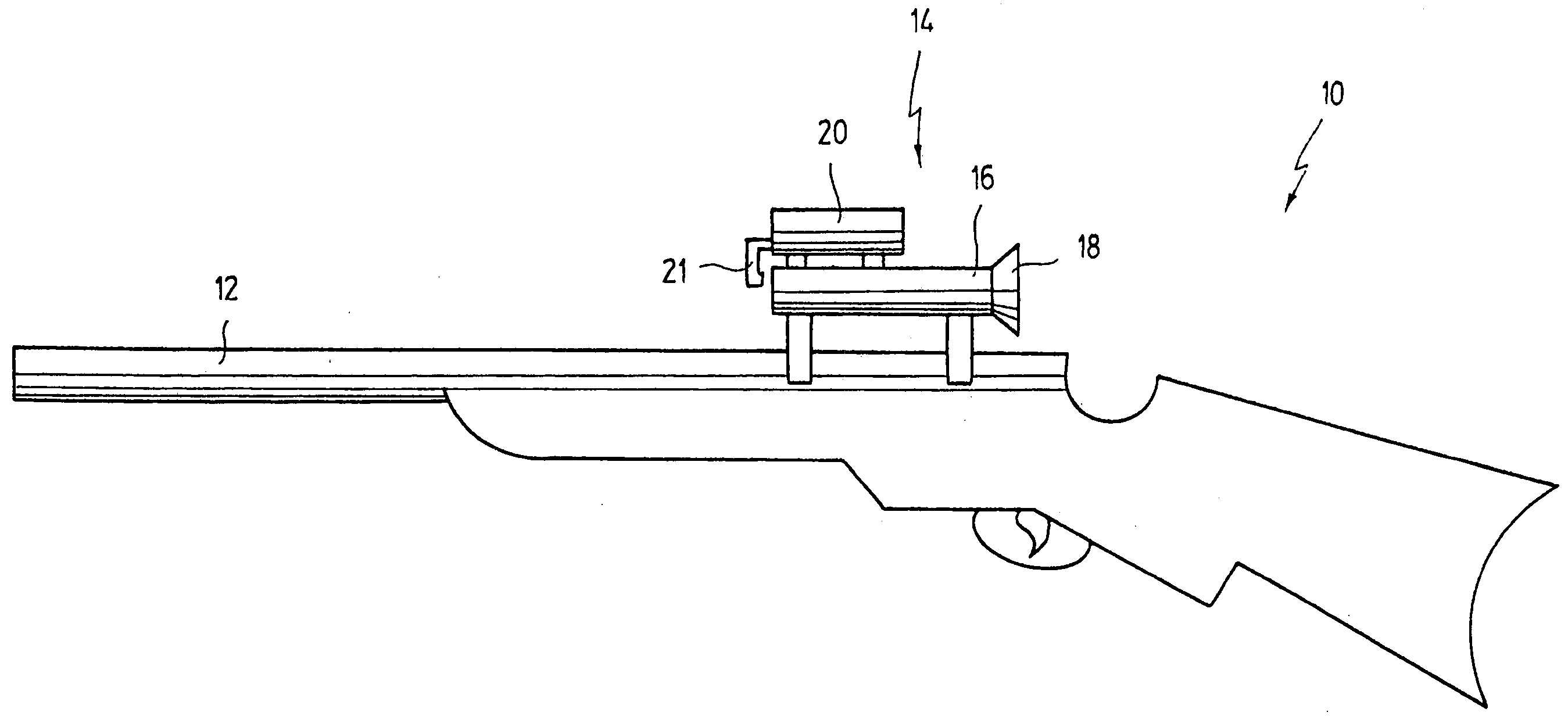
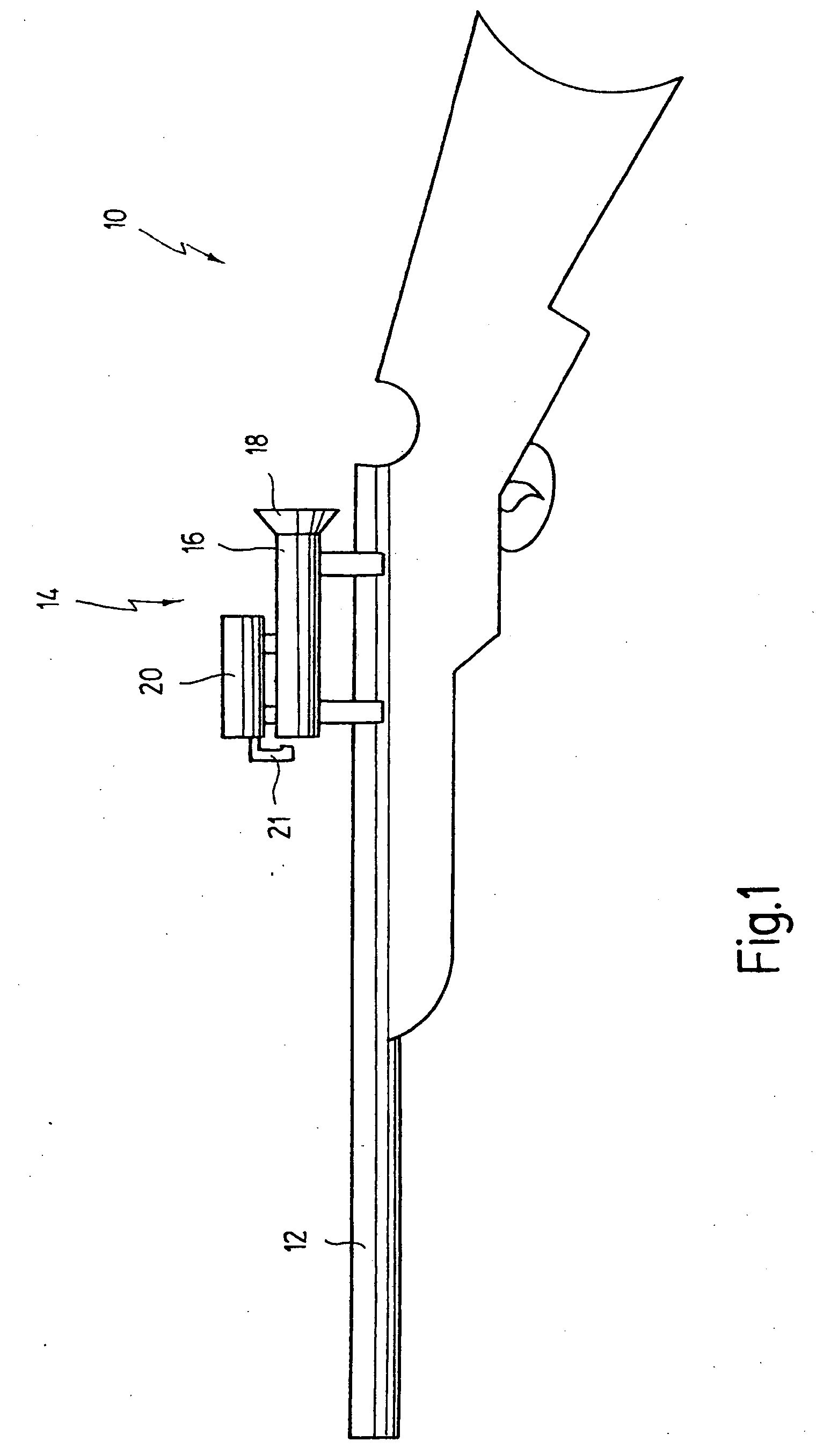
[0055]In FIG. 1, reference numeral 10 as a whole designates a portable firearm, in the embodiment shown, a rifle. It goes without saying that the invention is not limited to this kind of weapons. In particular, the invention may likewise be used in connection with other weapons, for example may be used with mobile launching installations for low-velocity projectiles, grenade launchers, for example.

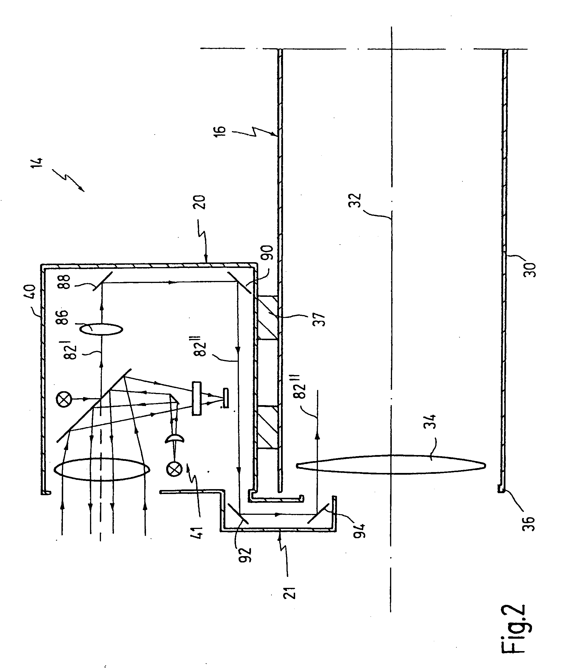
[0056]A sighting unit designated at 14 is mounted on a gun barrel 12 of portable firearm 10. Sighting unit 14 consists of an aiming telescope 16 having an eye piece 18. A detection unit 20 is mounted from above an aiming telescope 16, for example by plugging. Detection unit 20 comprises a unit for reflecting an image into the field of vision of aiming telescope 16. Unit 21 reflects light signals from the front into aiming telescope 16.

[0057]Detection unit 20 is used for detecting optical systems within a terrain. The term “optical system” is to be understood in the context of the present a...


PUM


Abstract

A method and an apparatus are used for detecting optical systems, for example a sniper within a terrain. The terrain is optically scanned by means of a movable mirror and the position of the optical system is determined from a measurement made by a laser unit and is optically displayed. The position of the optical system is directly determined from the measurement made by the laser unit by evaluating the intensity of a light beam from the laser unit, after having been reflected by an optical surface of the optical system. The position is optically reflected into the field of vision of a telescope. The apparatus comprises a laser unit having a movable mirror, a control unit for detecting the position of the optical system from a measurement made by the laser unit, and a device for optically displaying the position. The device for optically displaying is a telescope, and means are provided for optically reflecting the position of the optical system into the field of vision of the telescope.

Description

FIELD OF THE INVENTION[0001]The invention, generally, is related to the field of military weapons.[0002]More specifically, the invention is related to the field of methods and apparatuses for assisting the aiming at a hostile object with a weapon for launching low-velocity projectiles, in particular with a grenade launcher.[0003]Still more specifically, the invention is related to a method for detecting optical systems within a terrain, wherein the terrain is optically scanned by means of a movable mirror, the position of the optical system being determined from a measurement made by a laser unit and being optically displayed.[0004]The invention, moreover, is related to an apparatus for detecting optical systems within a terrain comprising a laser unit having a movable mirror, a control unit for detecting the position of the optical system from a measurement made by the laser unit, and a device for optically displaying the position.BACKGROUND OF THE INVENTION[0005]In the course of m...

Claims


Application Information

Patent Timeline
IPC IPC(8): G01B11/26G01S17/04
CPCG01S17/026G02B23/10G02B23/14F41G3/147G01S17/04
Inventor KUERBITZ, GUNTHER
Owner CARL ZEISS OPTRONICS
Why Eureka
Try Eureka