
Dynamic converter topology

a converter and topology technology, applied in the direction of power conversion systems, dc-dc conversion, dc source parallel operation, etc., can solve the problems of significant less than it is capable of having an efficiency that is low, the efficiency of the converter in doing so may be unacceptably low, and the selection of converters must be operated less efficiently

Inactive Publication Date: 2008-10-23
INTERSIL INC
View PDF3 Cites 44 Cited by
  • Summary
  • Abstract
  • Description
  • Claims
  • Application Information

AI Technical Summary

Problems solved by technology

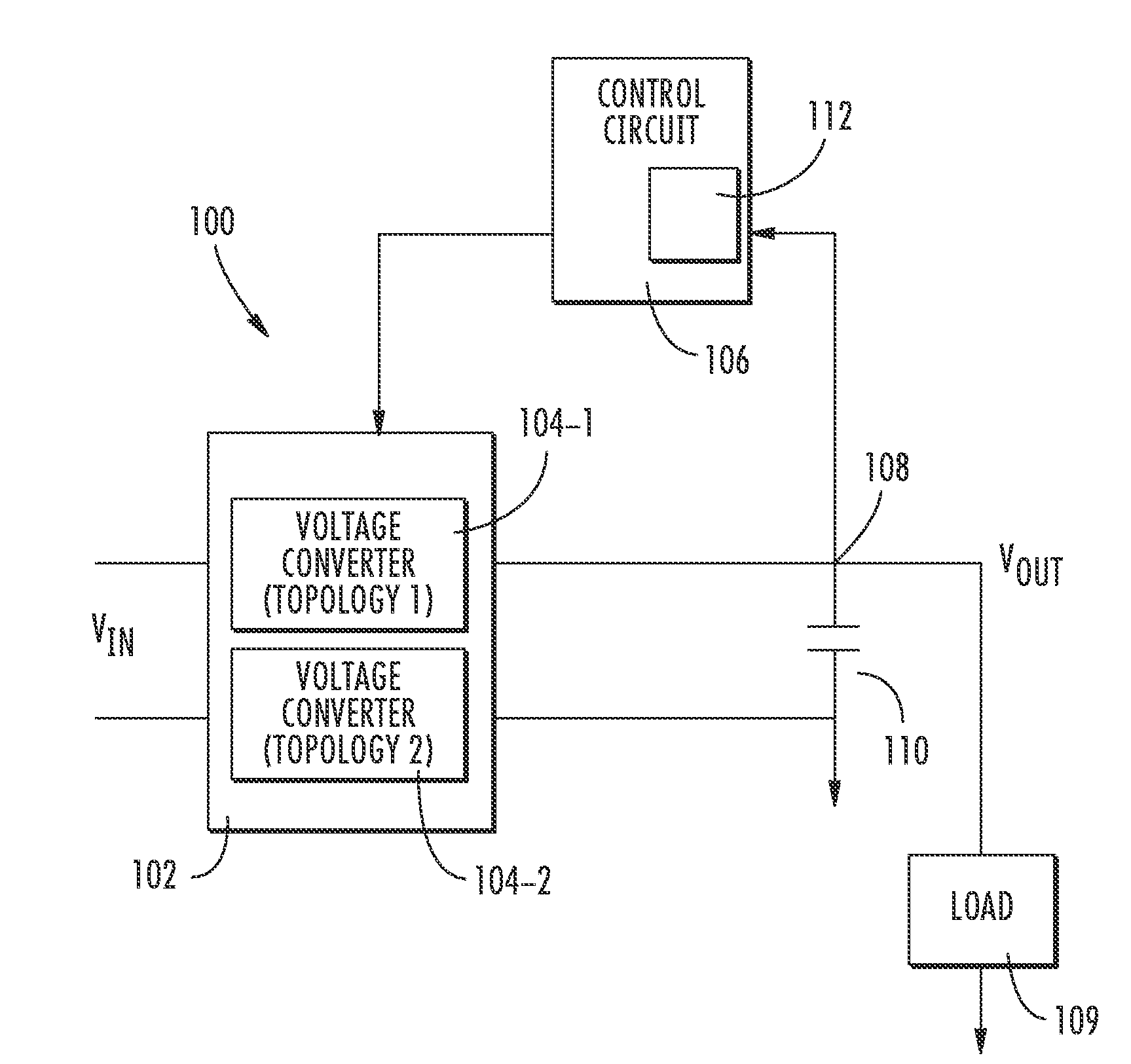
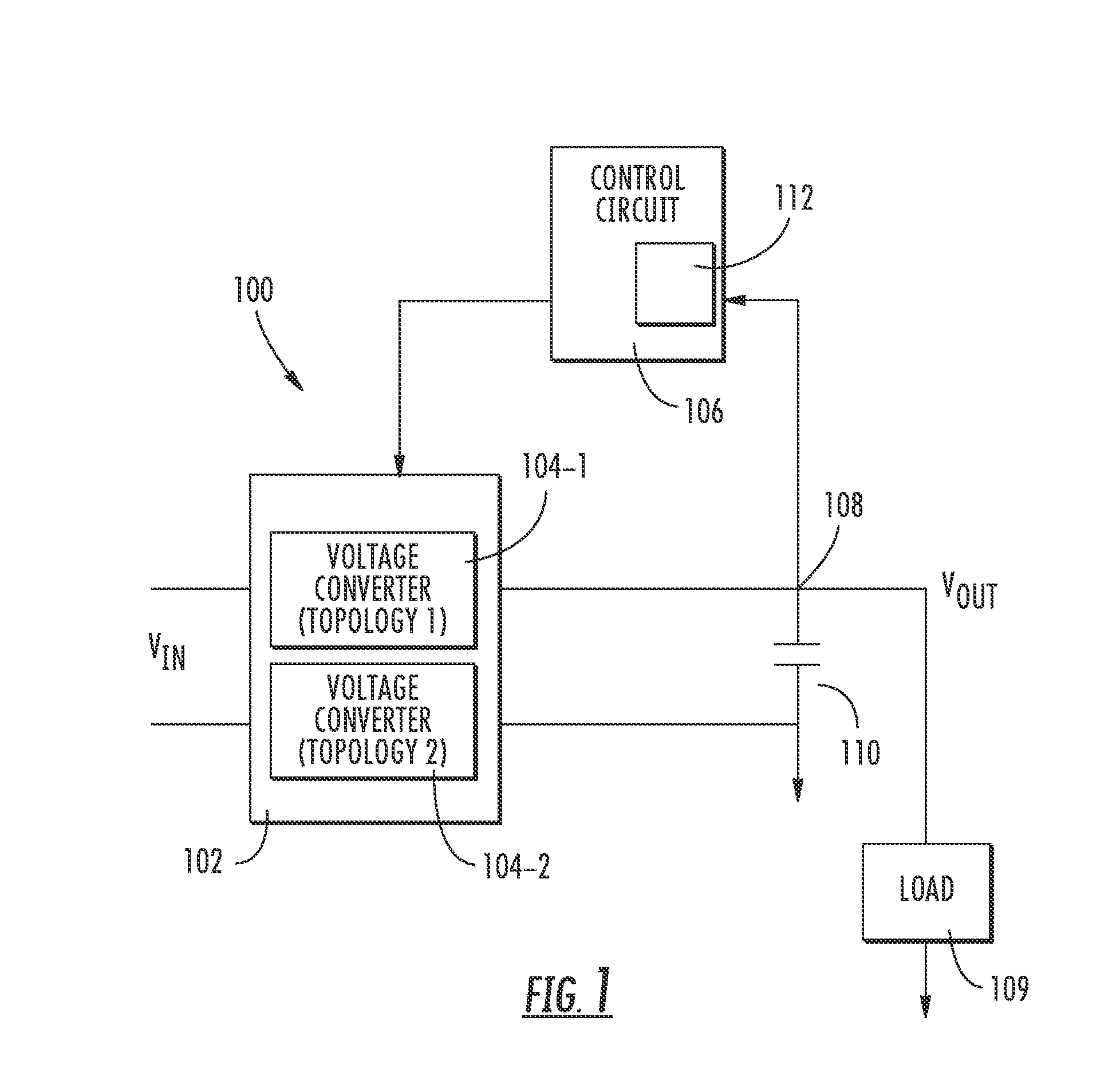
For example, a converter of a given topology providing an output that is significantly less than it is capable of may have an efficiency that is low.
If only 100 watts is needed at the output, the full-bridge converter can supply this required output level but the efficiency of the converter in doing so may be unacceptably low.
Under light load conditions, the selected converter must be operated less efficiently.

Method used


Image

  • Dynamic converter topology
  • Dynamic converter topology
  • Dynamic converter topology

Examples


Embodiment Construction

[0021]In the following detailed description, reference is made to the accompanying drawings, which form a part hereof, and in which is shown by way of illustration specific embodiments in which the inventions may be practiced. These embodiments are described in sufficient detail to enable those skilled in the art to practice the invention, and it is to be understood that other embodiments may be utilized and that logical, mechanical and electrical changes may be made without departing from the spirit and scope of the present invention. The following detailed description is, therefore, not to be taken in a limiting sense, and the scope of the present invention is defined only by the claims and equivalents thereof.

[0022]Embodiments of the present invention provide converters that operates efficiently under both normal loads and light loads by changing between circuit topologies based on the load needed at the then current time. In particular, in some embodiments a control circuit moni...


PUM


Abstract

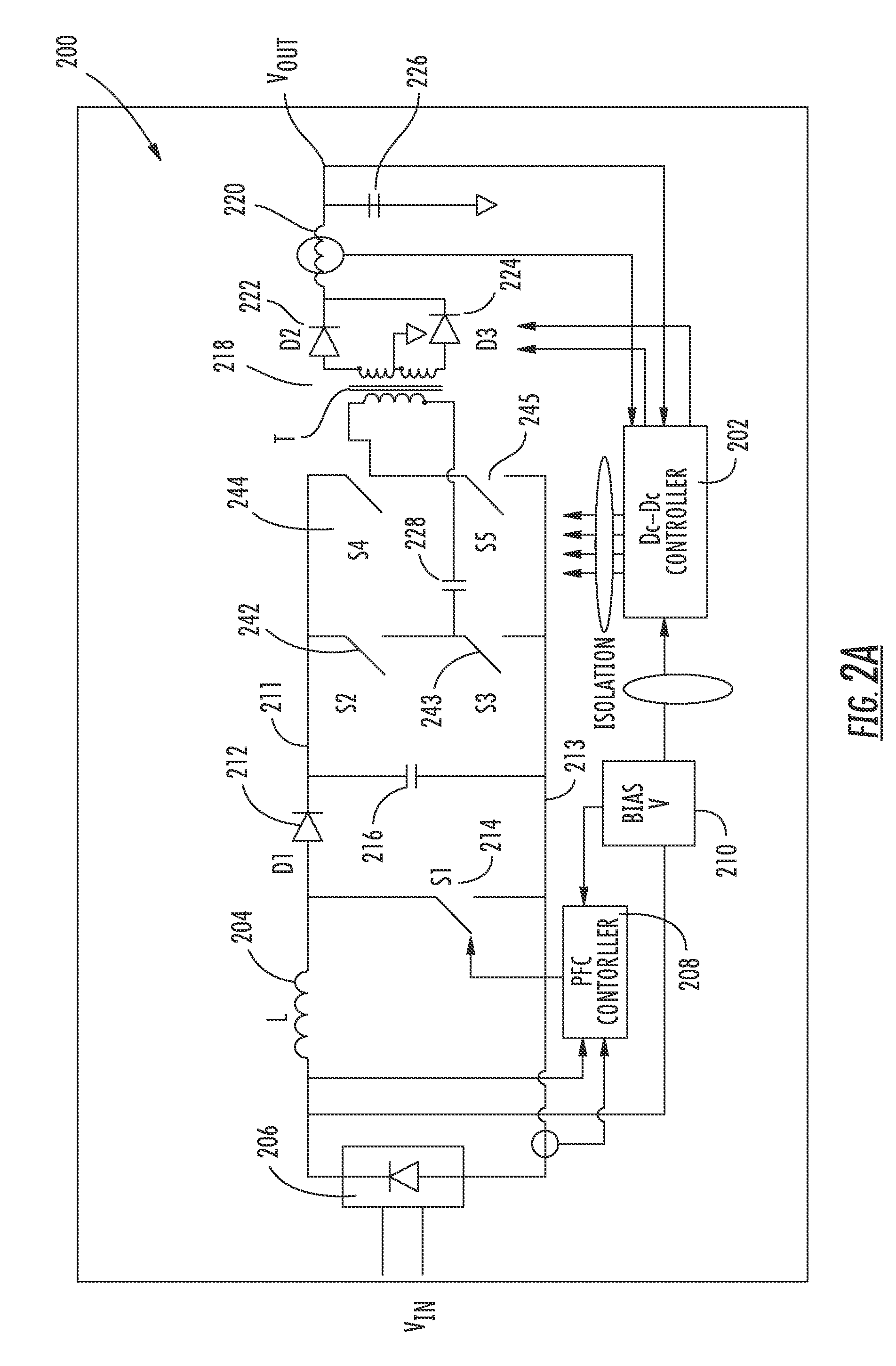
Methods and apparatus of dynamic topology power converters are provided. One method includes monitoring at least one variable of the power converter and based on the at least one monitored variable, using a converter topology selected between at least a full-bridge converter topology and a half-bridge converter topology to achieve an efficient operation at a then current operational load.

Description

CROSS REFERENCE TO RELATED CASES[0001]The present application claims priority to Provisional Application No. 60 / 925,382 filed on Apr. 20, 2007 and Provisional Application No. 60 / 916,172 filed on May 4, 2007, both of which are incorporated in there entirety in the present application.BACKGROUND[0002]Some electronic systems include power supplies for receiving an input voltage and converting this input voltage to a desired output voltage to be supplied to components in the electronic system that performs the desired function of the system.[0003]For example, a computer system includes a power supply that receives an input voltage and converts this input voltage to an output voltage that is applied to, for example, a motherboard, disk drives, a monitor as well as other components. Ideally, the power supply operates as efficiently as possible, where efficiency relates to the portion of input power received by the power supply that is converted into output power provided by the power supp...

Claims


Application Information

Patent Timeline
Patent Type & Authority Applications(United States)
IPC IPC(8): H02M3/335H02J1/00
CPCH02M3/33507H02M3/33569H02M3/337H02M3/33573H02M3/33571
Inventor MOUSSAOUI, ZAKI
Owner INTERSIL INC
Learn More