Cutting guide with internal distraction

a cutting guide and internal distraction technology, applied in the field of cutting guide with internal distraction, can solve the problems of increased loading on the medial joint compartment, varus or valgus defect in the tibia, increased loading on the lateral joint compartment,

Active Publication Date: 2008-10-23
HOWMEDICA OSTEONICS CORP
View PDF81 Cites 308 Cited by
  • Summary
  • Abstract
  • Description
  • Claims
  • Application Information

AI Technical Summary

Benefits of technology

[0014]In an alternative embodiment, the distractor is a screw slideably engaged with an opening in the first arm and threadably engaged with a threaded hole in the second arm. The step of manipulating the distractor includes rotating the screw so as to cause axial motion of the screw relative to the second arm. This method may further include forming a second cut in the proximal tibia at an angle relative to the first cut such that the second cut intersects the first cut so as to create a wedge of bone. The wedge of bone may then be removed from the proximal tibia so as to form a wedge-shaped opening in the proximal tibia. The screw is then rotated so as to cause the first arm and second arm to rotate toward each other so as to close the wedge-shaped opening in the proximal tibia. ...

Problems solved by technology

Such uneven weight bearing results from either a varus or valgus defect in the tibia.
A varus deformity generally results in increased loading on the medial joint compartment, while a valgus defect results in increased loading on the lateral joint compartment.
H...

Method used


Image

  • Cutting guide with internal distraction
  • Cutting guide with internal distraction
  • Cutting guide with internal distraction

Examples


Embodiment Construction

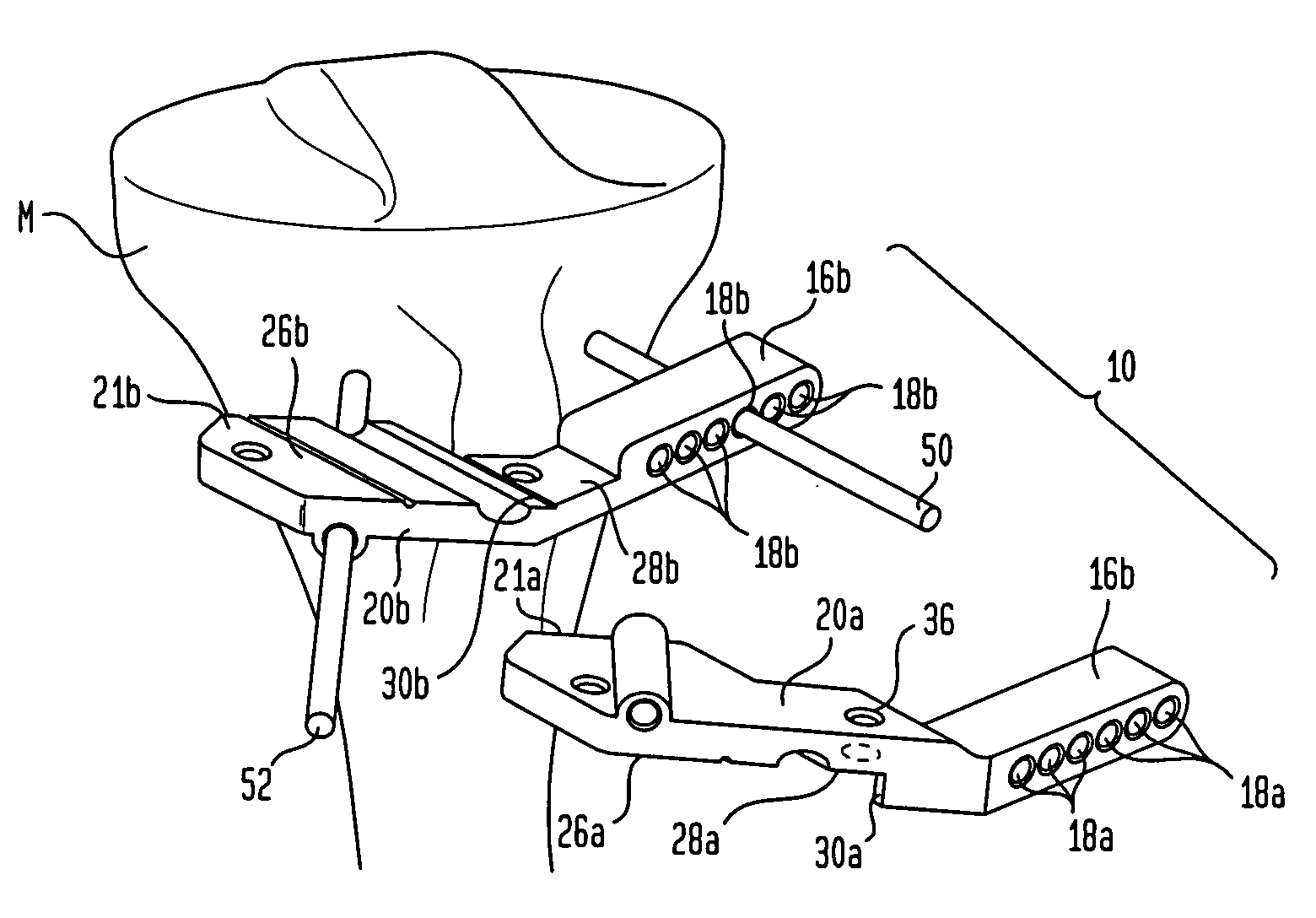
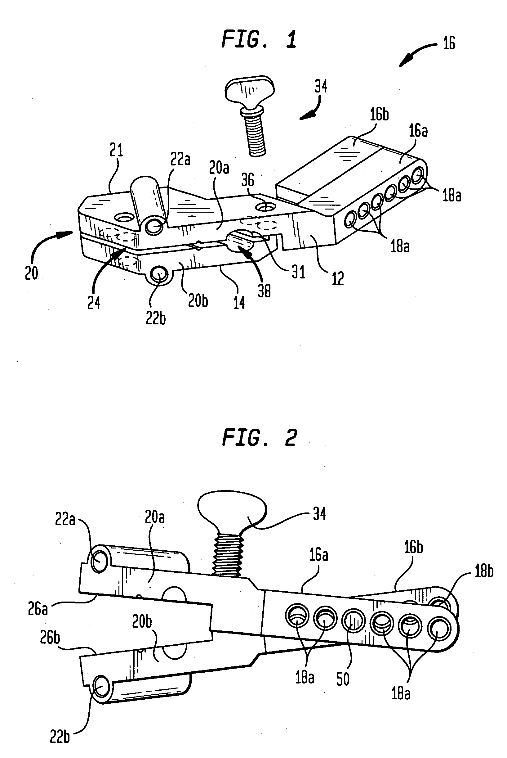
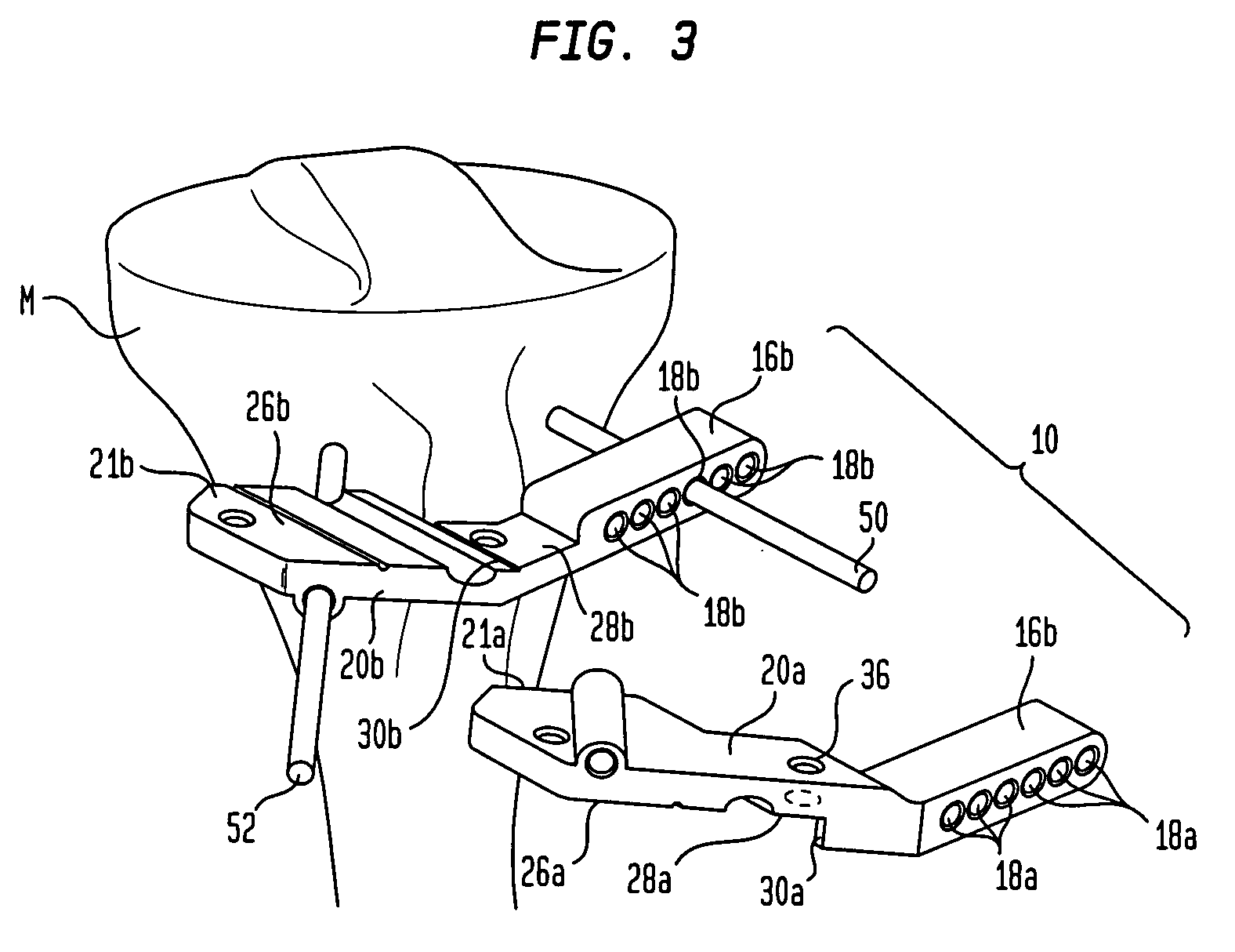
[0029]An exemplary embodiment of a cutting guide 10 according to an embodiment of the present invention is shown in FIG. 1. Generally, cutting guide 10 is adapted to be affixed to a bone surface, and, in the particular embodiment shown in FIG. 1, is adapted to be affixed to the anterior surface of the proximal portion of a human tibia. Cutting guide 10 includes a hinge portion 16 on one end and a guide portion 20 on another end.

[0030]Hinge portion 16 is adapted to be positioned partially over the patellar tendon which is associated with the proximal tibia and to extend toward a first side thereof. Guide portion 20 is adapted to contact a portion of the proximal tibia on a second side of the patellar tendon such that hinge portion 16 is spaced apart from the anterior surface of the proximal tibia at a distance adequate to prevent hinge portion 16 from contacting or otherwise interfering with the patellar tendon. By way of example, guide 10 is shown and described as being adapted for ...


PUM


Abstract

A cutting guide for performing a bone osteotomy procedure is disclosed. The cutting guide includes a first arm having a first cutting guide surface formed therein, a second arm having a second cutting guide surface formed therein pivotably connected to the first arm and a distractor operatively connected to the first arm. The cutting guide is adapted to be affixed to the bone such that the first cutting guide surface is open to the second cutting guide surface. The first arm and second arm are rotatable with respect to each other such that manipulation of the distractor creates a force between the first arm and the second arm causing rotation of the first arm and second arm relative to each other. A method for using the cutting guide in a bone osteotomy procedure is also disclosed.

Description

BACKGROUND OF THE INVENTION[0001]High tibial osteotomy (“HTO”) procedures have become well-established means of treating unicompartmental degenerative arthritis of the knee. This condition occurs due to uneven weight bearing of the femoral condyles on either of the medial or lateral joint compartments of the tibia. Such uneven weight bearing results from either a varus or valgus defect in the tibia. A varus or valgus defect occurs when the knee joint shifts either medially (valgus) or laterally (varus) with respect to the mechanical axis. It is generally accepted that the preferred location for the mechanical axis of the knee is at about 62% of the tibial plateau from medial to lateral. The process for determining the location of the mechanical axis is known in the art. A varus deformity generally results in increased loading on the medial joint compartment, while a valgus defect results in increased loading on the lateral joint compartment. A high-tibial osteotomy procedure uses on...

Claims


Application Information

Patent Timeline
IPC IPC(8): A61B17/56
CPCA61B17/8095A61B17/1764A61B2017/565A61B17/152
Inventor COLLAZO, CARLOS E.
Owner HOWMEDICA OSTEONICS CORP
Why Eureka
Try Eureka