Three-Dimensional Wiring Body for Mounting Electronic Component and Electronic Component Mounting Structure

Inactive Publication Date: 2008-11-06
FURUKAWA ELECTRIC CO LTD
View PDF1 Cites 11 Cited by
  • Summary
  • Abstract
  • Description
  • Claims
  • Application Information

AI Technical Summary

Benefits of technology

[0022]The present invention provides an electronic components mounted wiring body which comprises a flat wiring body on which a plurality of electronic components is mounted, and a plurality of base members on which the flat wiring body is mounted, wherein the flat wiring body includes arrangement direction changing folds which are bent so as to change an arrangement direction of the electronic components, and wherein the base members include arrangement direction changing members which fix the arrangement direction changing folds. Thus, the present invention reduces the time-consuming operations that are required in the conventional art to individually mount and wire electronic components on the base structure at respective positions which is integrally formed in a complicated three dimension. In addition, unlike the conventional art, there is no need for preparing a variety of base structures according to product kinds. The present invention can be adapted to different product kinds by simply combining and assembling a reduced set of standard base members, thus increasing the freedom of design.
[0023]According to the present invention, the

Problems solved by technology

However, the above mentioned conventional art disclosed in the respective patent documents generally has two problems: The first problem is associated with the operability of the mounting and assembling.
In the case of patent documents D1 and D2, the light emitting structure using a wiring circuit in the form of electric wires or bus bars requires time-consuming and troublesome operations for mounting and wiring LEDs on a complicated and integrally formed, three-dimensional base of the structure.
Similarly in the case of patent documents D3 to D6, the light emitting structure using a flat wiring body requires time-consuming and troublesome operations for positioning LEDs at respective steps and fixing the flat wiring body.
Thus in either case, the mounting

Method used


Image

  • Three-Dimensional Wiring Body for Mounting Electronic Component and Electronic Component Mounting Structure
  • Three-Dimensional Wiring Body for Mounting Electronic Component and Electronic Component Mounting Structure
  • Three-Dimensional Wiring Body for Mounting Electronic Component and Electronic Component Mounting Structure

Examples


Embodiment Construction

[0076]The present invention will now be described with respect to an embodiment thereof taken in conjunction with the drawings.

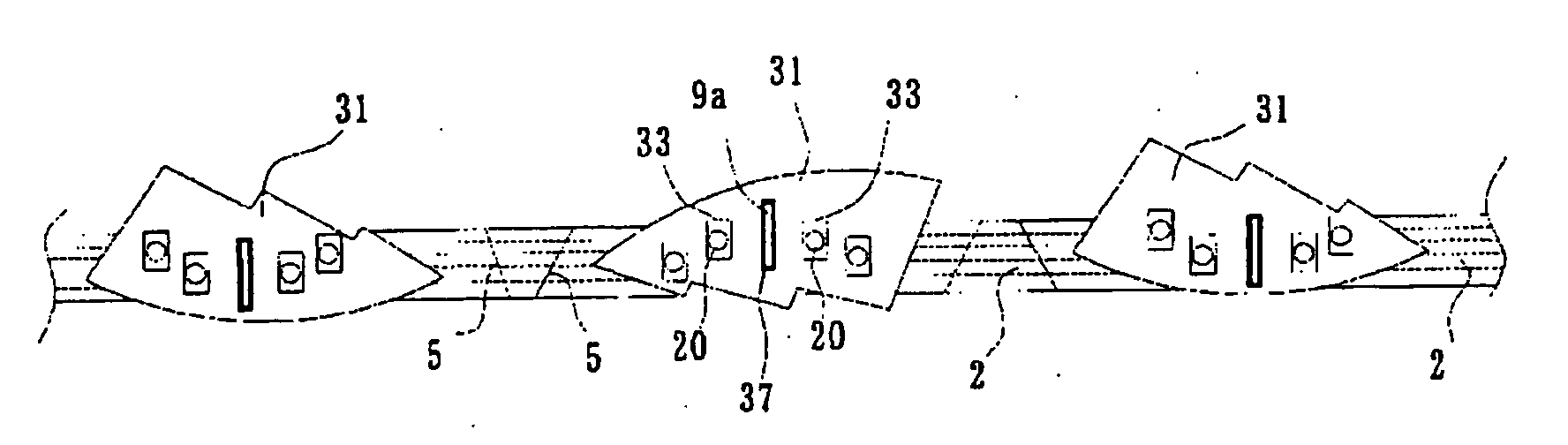
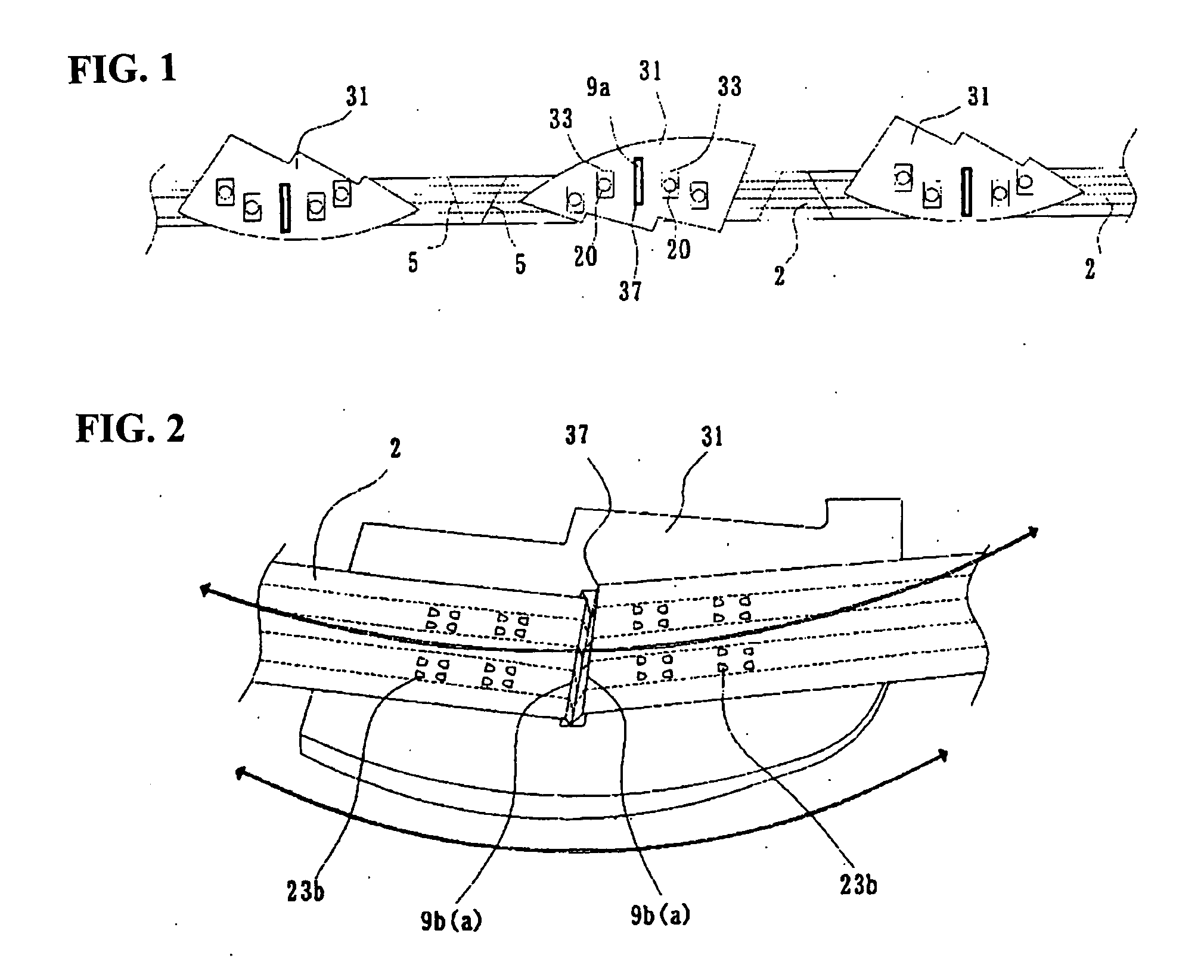
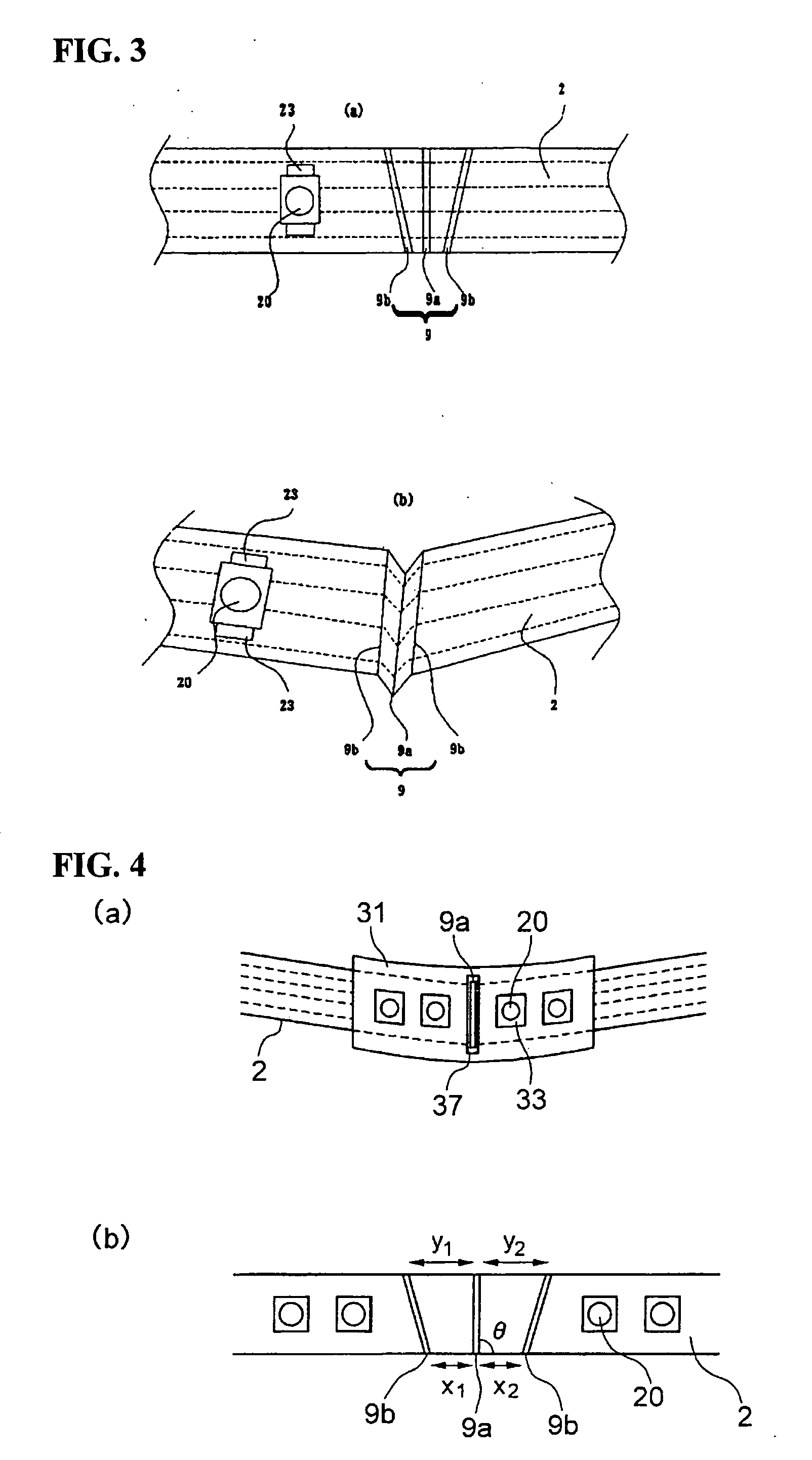
[0077]FIGS. 1 to 3 show an electronic components mounted wiring body according to the embodiment of the present invention. Specifically, FIG. 1 is a plan view showing base members 31 mounted to a flat wiring body 2. FIG. 2 is a rear perspective view showing the flat wiring body 2 and one of the base members 31 in FIG. 1, as viewed from the rear. FIG. 3 is a plan view of the flat wiring body 2.

[0078]In the embodiment of the invention, the electronic component mounted wiring body is assembled by mounting a plurality of the base members 31 to the flat wiring body 2, on which a plurality of electronic components 20 is mounted. According to a feature of the present invention, each base member 31 has an arrangement direction changing member 37 to change the arrangement direction of the electronic components 20 of the flat wiring body 2. This feature will be descri...


PUM


Abstract

An electronic components mounted wiring body (10) comprises a flat wiring body (2) on which a plurality of electronic components (20) is mounted, and a plurality of base members (31) on which the flat wiring body (2) is mounted. The flat wiring body (2) has arrangement direction changing folds (9), each of which is designed to change an arrangement direction of the electronic components (20) of the flat wiring body (2). Each base member (31) has an arrangement direction changing member (37) which is designed to fix the arrangement direction changing fold (9). The base members (31) are joined using joining members (32) so that the electronic components mounted wiring body (10) is configured into a three-dimensional shaped electronic components mounting structure (1).

Description

TECHNICAL FIELD[0001]The present invention relates to an electronic components mounted wiring body for use in vehicles and others as well as an electronic components mounting structure.BACKGROUND ART[0002]In recent years, light emitting diodes (LEDs) have been widely used for lamps on the front and rear of automobiles. An Electric wire, bus bar or flat wiring body has been used to form a wiring circuit or power feed circuit for such LEDs. For instance, a light emitting structure in which LEDs that are connected to electric wires are arranged in three dimensional steps is known (see patent documents D1 and D2). Also known is another light emitting structure in which LEDs that are connected to a flat wiring body are arranged in a three dimensional steps (see patent documents D3 to D6).[0003]Patent Document D1: Japanese Patent Application Publication 2000-243110[0004]Patent Document D2: Japanese Patent Application Publication 2002-245812[0005]Patent Document D3: Japanese Patent Applica...

Claims


Application Information

Patent Timeline
IPC IPC(8): H05K1/00
CPCH05K1/0281H05K1/189H05K3/0058H05K2201/055H05K2201/10106H05K2201/2009
Inventor ENOMOTO, NORITSUGUUTSUNOMIYA, HIROFUMIKAMIMURA, KENMOTOMURA, SHIGEKIAOYAGI, SHIGEHARUTAKEDA, JUNICHI
Owner FURUKAWA ELECTRIC CO LTD
Why Eureka
Try Eureka