
Medical Valve with Expandable Member

a technology of medical valves and expandable parts, which is applied in the field of medical valves, can solve the problems of blood leakage proximal into various parts of the valve, compromising affecting the sterility of the valve,

Inactive Publication Date: 2008-11-06
NYPRO INC
View PDF0 Cites 15 Cited by
  • Summary
  • Abstract
  • Description
  • Claims
  • Application Information

AI Technical Summary

Benefits of technology

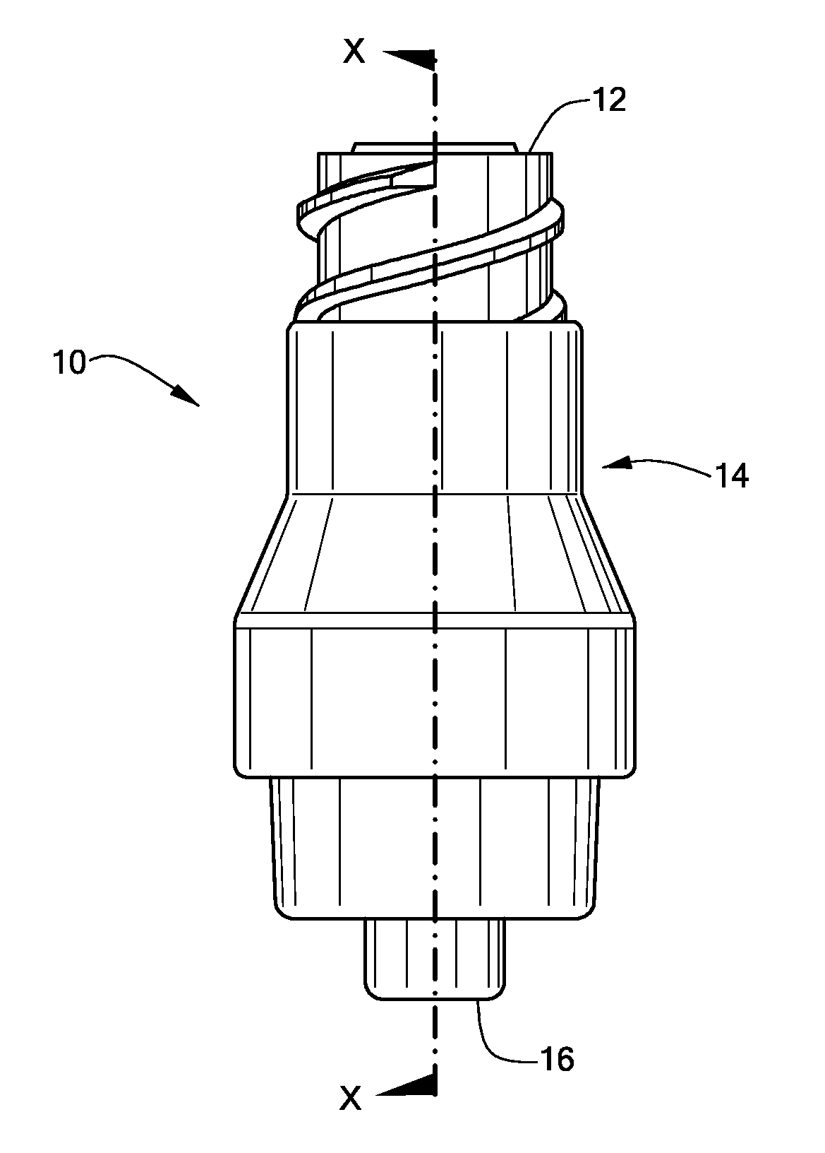
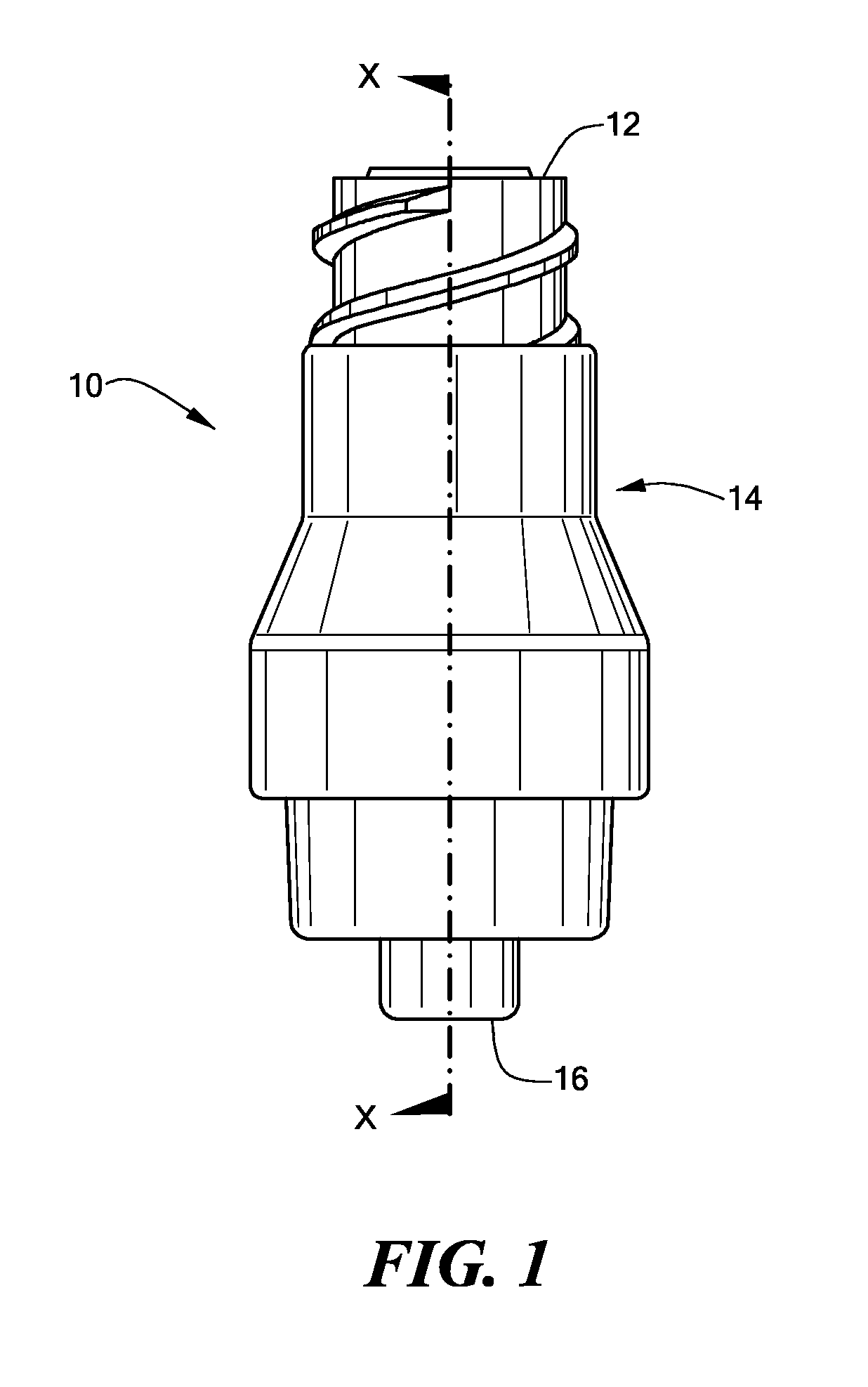
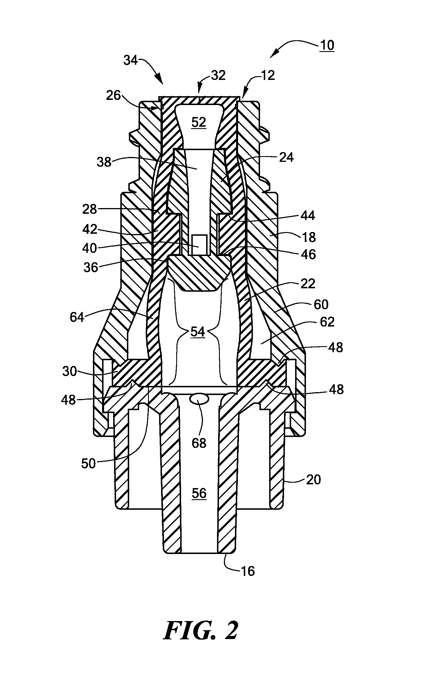
The invention is a medical valve that can switch between a closed mode and an open mode. It includes a resilient member that can expand to a larger volume in the open mode compared to the closed mode. The valve has a housing and a resilient member that form a fluid channel between the inlet and outlet. The resilient member has a normal volume when in the closed mode and an expanded volume when in the open mode. The valve can control fluid flow through the valve and is activated by a blunt tip. The invention provides a medical valve that can reliably control fluid flow and can be easily switched between closed and open modes.

Problems solved by technology

Problems arise, however, when the syringe is withdrawn from the valve.
More particularly, a back pressure (i.e., a proximally directed pressure) produced by the withdrawing syringe undesirably can cause blood to leak proximally into various parts of the valve.
In addition to coagulating and impeding the mechanical operation of the valve, blood in the valve also compromises the sterility of the valve.
In addition to requiring more parts for this purpose, another type of valve forces a compressible member into a reduced diameter lumen, consequently forcibly reducing the volume of the fluid chamber.
Both noted purported solutions create additional problems.
In particular, adding more parts increases the manufacturing cost of the valve.
For example, more parts typically increases material cost, assembly time, and testing time.
In other words, a defect in one of the additional parts can adversely affect the mechanical operation of the valve.
Furthermore, accurately forcing a compressible member into a reduced diameter lumen after such member has expanded can be difficult, thus possibly rendering the valve unusable.

Method used


Image

  • Medical Valve with Expandable Member
  • Medical Valve with Expandable Member
  • Medical Valve with Expandable Member

Examples


Embodiment Construction

[0022]In illustrative embodiments of the invention, a medical valve is configured to substantially eliminate fluid drawback when a nozzle or syringe is withdrawn from it. In fact, in some embodiments, the valve is expected to produce a positive, distally directed pressure when a nozzle or syringe is withdrawn. Such pressure necessarily should prevent non-negligible amounts of fluid from being drawn into the valve.

[0023]To these ends, illustrative embodiments of the medical valve have an interior fluid chamber that is larger when it is in an open mode (i.e., permitting fluid flow, also referred to as “open position”), than when it is in a closed mode (i.e., preventing fluid flow, also referred to as “closed position”). More specifically, the fluid chamber is formed from a resilient member that, when transitioning from the closed mode toward the open mode, expands from its normal (i.e., relaxed) state. This expansion consequently increases the volume of fluid that the fluid chamber ca...


PUM


Abstract

A medical valve has a resilient member that is forcibly expanded to an expanded volume from a normal volume. Specifically, the valve operates in a closed mode that prevents fluid flow, and an open mode that permits fluid flow. To these ends, the valve has a housing having an inlet and an outlet, and the noted resilient member within the housing. The resilient member and housing form a fluid channel between the inlet and the outlet. The fluid channel at least in part extends through the resilient member. The fluid channel has a given portion formed by a variable volume portion of the resilient member. The variable volume portion has a normal volume when in the closed mode, and an expanded volume when the open mode. The expanded volume is greater than the normal volume.

Description

PRIORITY[0001]This patent application is a continuation of and claims priority from all priority dates of U.S. patent application Ser. No. 10 / 224,299, filed Aug. 20, 2002, and entitled “MEDICAL VALVE WITH EXPANDABLE MEMBER” (attorney docket number 1600 / 149). As a consequence of this priority claims, this patent application also claims priority to U.S. provisional patent application No. 60 / 314,210, filed Aug. 22, 2001, and entitled, “MEDICAL VALVE WITH VARIABLE VOLUME CHAMBER.” The disclosures of each of these applications are incorporated herein, in their entirety, by reference.FIELD OF THE INVENTION[0002]The invention generally relates to medical valves and, more particularly, the invention relates to reducing backflow through medical valves.BACKGROUND OF THE INVENTION[0003]Medical valving devices typically valve fluids injected into and withdrawn from a patient. One exemplary type of medical valving device, known in the art as a “catheter introducer,” maintains a sealed port for a...

Claims


Application Information

Patent Timeline
Patent Type & Authority Applications(United States)
IPC IPC(8): A61M39/06A61M39/00A61M5/168A61M39/26
CPCA61M39/26A61M2039/263A61M2039/267
Inventor NEWTON, BRIAN L.COTE, ANDREW L.
Owner NYPRO INC
Learn More